
Related Manuals for CleaverBrooks FLX Series


Summary of Contents for CleaverBrooks FLX Series
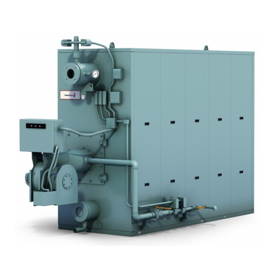
- Page 1 MODEL PACKAGED BOILER 1,500,000 to 12,000,000 Btu/hr Hot Water and Steam Fuel: Light Oil, Gas or Combination Manual Part No. 750-177 R6 5/2014...
- Page 2 MODEL FLX PACKAGED BOILER Operation, Service, and Parts Manual 1,500,000 to 12,000,000 Btu/hr Fuel: Light Oil, Gas or Combination Cleaver-Brooks 2014 Please direct purchase orders for replacement manuals to your local Cleaver-Brooks authorized representative Manual Part No. 750-177 R6 Revised 5/2014 Printed in U.S.A.
- Page 3 WARNING ! DANGER DO NOT OPERATE, SERVICE, OR REPAIR THIS EQUIPMENT UNLESS YOU FULLY UNDERSTAND ALL APPLICABLE SECTIONS OF THIS MANUAL. DO NOT ALLOW OTHERS TO OPERATE, SERVICE, OR REPAIR THIS EQUIPMENT UNLESS THEY FULLY UNDERSTAND ALL APPLICABLE SECTIONS OF THIS MANUAL. FAILURE TO FOLLOW ALL APPLICABLE WARNINGS AND INSTRUCTIONS MAY RESULT IN SEVERE PERSONAL INJURY OR DEATH.
-
Page 4: Table Of Contents
TABLE OF CONTENTS Chapter 1 Basics of Flexible Watertube Operation A. General ............1-1 B. - Page 5 Chapter 4 Sequence Of Operation A. General ............4-1 B.
- Page 6 Chapter 7 Inspection And Maintenance A. General ............7-1 B.
-
Page 7: General
CHAPTER 1 General Description A. General 1-1 B. The Boiler 1-2 C. Construction 1-2 D. Steam Controls (All Fuels) 1-2 E. Hot Water Controls (All Fuels) 1-4 A. General CAUTION ! DANGER This manual covers Cleaver-Brooks Model FLX boilers in sizes ranging from 1,500,000 The care taken in placing the boiler into initial service to 12,000,000 Btu/hr input. -
Page 8: The Boiler
Chapter 1 General Description B. The Boiler The Cleaver-Brooks Model FLX is a five-pass steel boiler with flexible watertubes formed and arranged so as to direct the flow of combustion gases through the boiler. The pressure vessel conforms to Section I or IV of the ASME code. -
Page 9: Construction
General Description Chapter 1 C. Construction Steam boilers designed for 15 psig and hot water boilers designed for 250F at 160 psi or less are constructed in accordance with Section IV, Heating Boilers, of ASME Code. Steam boilers designed for 150 psig are constructed in accordance with Section I, Power Boilers, of the ASME Code. -
Page 10: Hot Water Controls (All Fuels)
Chapter 1 General Description 8. Safety Valve(s): Prevent buildup over the design pressure of the pressure vessel. The size, rating and S U P P O RT F R O M B U I L D I N G C O N S T R UC T I O N number of valves on a boiler is determined by the DISCHARGE OPENING MUST BE EQUAL TO OR LARGER THAN... - Page 11 General Description Chapter 1 7. Auxiliary Low Water Cutoff (Not Shown) (Optional): Breaks the circuit to stop burner operation if the water level in the boiler drops below the master low-water cutoff point. 8. Safety Valve(s): Prevent buildup over the design pressure of the pressure vessel. The size, rating and number of valves on a boiler is determined by the ASME Boiler Code.
- Page 12 Chapter 1 General Description 750-177...
-
Page 13: Profire V Burner
CHAPTER 2 Profire V Burner A. Introduction 2-1 B. Firing Head 2-4 C. Oil System 2-4 D. Gas System 2-7 E. Installation 2-9 F. Startup and Operation 2-19 G. Adjustments 2-26 H. Gas System 2-34 I. Oil System 2-37 J. Combination Gas-Oil System 2-39 K. - Page 14 Chapter 2 Profire V Burner OPERATING CONTROLS - PANEL The burner control panel may be integral to the burner or remote, and contains: a flame safeguard programming control, motor relays (starters), and terminal strips mounted internally on a panel subbase.Lights, switches, and a control circuit breaker are mounted externally on the panel. The following table lists typical panel items.
- Page 15 Profire V Burner Chapter 2 and fuel metering valves increase the firing rate. Optional “CAM” trim provides additional precision to the air/ fuel mix with the use of several discrete set point adjustments across the modulation range. Further combustion efficiency may be achieved with the use of parallel positioning controls which use multiple directly-coupled actuators (linkeageless) to position the air damper, fuel metering valves and, if applicable, flue gas recirculation (FGR) across the modulation range.
-
Page 16: Firing Head
Chapter 2 Profire V Burner B. FIRING HEAD Two side access covers provide access to the firing head internal components. Figure 2-1 shows a a radial spud firing head typically used on watertube applications GAS MANIFOLD MOUNTING FLANGE AIR BAFFLE CHOKE RING NOZZLE BODY AND TIP... - Page 17 Profire V Burner Chapter 2 OPERATION: Fuel oil is delivered to the fuel pump, either by gravity, fuel pump suction, or by a circulating pump, through a fuel oil filter. Pressurized fuel returns to the storage tank until the two solenoid valves open. Straight oil burners (VL13-55) employ direct spark ignition where the oil is ignited when the oil solenoid valves open and the spray contacts the electrical discharge from the direct spark electrodes.
- Page 18 Chapter 2 Profire V Burner NODULATING MOTOR FUEL UNIT PRESSURE TAP NOZZLE FUEL UNIT PRESSURE TAP FUEL UNIT OIL SUPPLY OIL RETURN TO TANK N.C. VALVES METERING VALVE Figure 2-3: Full Modulation Oil System with Integral Pump & Return Flow Nozzle (V13-55) MODULATING MOTOR NOZZLE...
-
Page 19: Gas System
Profire V Burner Chapter 2 D. GAS SYSTEM Gas is introduced into the combustion zone from a circular manifold through multiple ports in the manifold.Firing rate is determined by the size and number of ports, by manifold pressure, and by combustion zone pressure. The firing rate is regulated by a rotary, butterfly-type throttling valve at the manifold inlet. - Page 20 Chapter 2 Profire V Burner Figure 2-5: Typical Gas Train for Full Modulation System (V13-34) Figure 2-6: Typical Gas Train for LHO/LHL Systems (V35-63) & Full Modulation Systems (V35-168) 750-177...
-
Page 21: Installation
Profire V Burner Chapter 2 PILOT GAS TRAIN COMPONENTS Models VL 60-168 as well as all VG and VLG models are supplied with a gas pilot system. Oil only models VL 13-55 are supplied with direct spark ignition. Gas Pilot Valve A solenoid valve that opens during the ignition period to admit fuel to the pilot. - Page 22 Chapter 2 Profire V Burner OIL PIPING The oil only (VL) and gas-oil (VLG) model burners use pressure atomization. Fuel oil is provided by a burner mounted fuel pump directly coupled to the blower motor via a flexible coupling for models V13-55. A remote pump is used for models V60-168.
- Page 23 Profire V Burner Chapter 2 Figure 2-8: Typical No. 2 Oil Loop Single Burner Figure 2-9: Multiple Burners with Separate Suction Lines 750-177 2-11...
- Page 24 Chapter 2 Profire V Burner Figure 2-10: Typical Oil Loop for Multiple Burners with Transfer Pump Figure 2-11: Typical Installation Using Day Tank 2-12 750-177...
- Page 25 Profire V Burner Chapter 2 Figure 2-12: Typical Flooded Loop System GAS PIPING Refer to Figures 2-5 through 2-6 for typical gas piping arrangements. Normally, the control train is ordered to suit a particular code or insurance regulation, such as UL/cUL, FM, or GAP . Gas service and house piping must supply the quantity of gas demanded by the unit at the pressure required at the burner gas train inlet.
- Page 26 Chapter 2 Profire V Burner INSTALLATION CHECKLIST All burners are carefully assembled and tested at the factory, but before being placed in service all connectors should again be checked for looseness caused during shipment. Check: a. Electrical terminals in the control panel and on all electrical components. b.
- Page 27 Profire V Burner Chapter 2 LOW-HIGH-LOW MOD - LOW or 60% DAMPER PURGE Combustion Air Pressure Atomization: Two solenoid type blade damper safety shut off oil valves initiate the flow of oil controlled by a two position, Safety shut off valve(s) are from the high pressure pump to the nozzle.
- Page 28 Chapter 2 Profire V Burner LOW-HIGH-LOW MOD - OPEN DAMPER PURGE Combustion Air Pressure Atomization: Two solenoid type safety blade damper shut off oil valves initiate the flow of oil from the high controlled by a two position, Safety shut off valve(s) are pressure pump to the nozzle.
- Page 29 Profire V Burner Chapter 2 FULL MODULATION - OPEN DAMPER PURGE Combustion Air Pressure Atomization: Two solenoid type safety shut off oil valves initiate the flow of oil from the high A two blade damper is controlled by a pressure pump to a return flow nozzle. In the return proportional modulating actuator (or line from the nozzle an adjustable oil metering valve motor) with mechanical linkage.
- Page 30 Chapter 2 Profire V Burner PARALLEL POSITIONING Combustion Air Pressure Atomization: Two solenoid type safety shut off oil valves initiate the flow of oil from the high pressure pump to a return flow nozzle. In the return line from the nozzle is an adjustable oil metering Safety shut valve(s)
-
Page 31: Startup And Operation
Profire V Burner Chapter 2 F. Startup and Operation When the installation is complete and all electrical, fuel, water, and vent stack connections are made, make certain the connections are tight. The operator should become familiar with the burner, boiler controls and components. - Page 32 Chapter 2 Profire V Burner When the conditions covered above and in Section 2 are assured, the burner is ready for firing. Refer to Section E for starting and operating information. Oil Burners Prior to initial firing, oil flow and pressure should be verified. If the burner is a dual fuel model, make certain that the main gas shutoff cock is closed and the fuel selector switch is set to OIL.
- Page 33 Profire V Burner Chapter 2 WARNING ! DANGER TO PREVENT POSSIBLE SERIOUS INJURY OR DEATH, READ THE FLAME SAFEGUARD MANUAL AND FULLY UNDERSTAND ITS CONTENT BEFORE ATTEMPTING TO OPERATE THIS EQUIPMENT. WARNING ! DANGER SHOULD A STARTING FAILURE OCCUR FOR ANY REASON, COMBUSTIBLE FUMES MAY FILL THE COMBUSTION CHAMBER.
- Page 34 Chapter 2 Profire V Burner ulator spring. Normal setting is 4” to 6” W.C. 4. Perform a pilot turndown test by reducing the pilot pressure very slowly until the scanner looses sight ofthe flame and gives a flame lockout, then reset the adjustment to normal level. Note the minimumpressure level. 5.
- Page 35 Profire V Burner Chapter 2 If a high or low gas pressure condition occurs while firing on gas, the burner shuts down as in Automatic Shutdown. Condition must be corrected and the respective gas pressure switch manually reset before the burner will fire again on gas.
- Page 36 Chapter 2 Profire V Burner 11. Do not repeat unsuccessful light off attempts without rechecking burner and pilot adjustment. Vent fuelvapors from the combus- tion chamber after each unsuccessful light off attempt. 12. Set the gas low fire rate by adjusting the butterfly valve and air linkage. 13.
- Page 37 Profire V Burner Chapter 2 The burner should be set up and maintained to yield smoke spot levels less than a #1 spot (ASTM D2156 Shell-Bacharach Scale) to minimize soot buildup in the boiler. Do not disturb established low fire adjustment. Allow the burner to return to low fire position before adjusting high or intermediate settings.
-
Page 38: Adjustments
Chapter 2 Profire V Burner Safety shutdown caused by ignition or flame failure will actuate a red indicator light and energize an audible alarm (if so equipped). If the programmer has a non-recycling interlock circuit, any interruption in this circuit during the pre-purge or firing cycle will cause a safety shutdown. - Page 39 Profire V Burner Chapter 2 TEST EQUIPMENT The following test equipment should be used to set up and adjust the burner correctly: • Combustion analyzer with O indication. • U-Tube manometer, or pressure gauge, to measure gas pressures (Main and Pilot), vacuum and pressure gauges for oil. •...
- Page 40 Chapter 2 Profire V Burner ELECTRODE END TIP TO TUBE WITHIN 1.00 " GAP OF .16" TUBE END 14.18 Figure 2-13: Direct Spark Ignition- Oil Only BURNER PILOT SETTINGS To ensure reliable and safe burner performance, the location and gap setting of the electrodes, and the relative positions of the burner nozzle, diffuser, and air baffle components must be set correctly.
- Page 41 Profire V Burner Chapter 2 ELECTRODE END TIP TO TUBE WITHIN 1.00 " GAP OF .16" TUBE END 14.18 Figure 2-14: Gas Pilot Measure the position of the tip of the nozzle to the diffuser and compare to the following drawer assembly drawings.
- Page 42 Chapter 2 Profire V Burner 5/32" BETWEEN INNER EDGES OF ELECTRODE WIRES 7/16" FROM CENTER OF OIL NOZZLE TIP TO BOTTOM EDGE .25" NOZZLE TIP OF ELECTRODE WIRES TO OUTER EDGE OF ELECTRODE WIRES .25" FROM NOZZLE TIP TO REAR FACE OF DIFFUSER 1.89"...
- Page 43 Profire V Burner Chapter 2 1.81" REAR FACE OF DIFFUSER TO FRONT FACE OF AIR BAFFLE 656-10215-000 Figure 2-18: Drawer Assembly for (VG) Gas Only (V35-55) - Watertube 5/32" BETWEEN INNER EDGES OF 7/16" FROM CENTER ELECTRODE WIRES OF OIL NOZZLE TIP .25"...
- Page 44 Chapter 2 Profire V Burner Figure 2-20: Drawer Assembly for (VLG) Gas/Oil (V35-55) - Watertube .16" REAR FACE OF DIFFUSER TO FRONT FACE OF AIR BAFFLE Figure 2-21: Drawer Assembly for (VG) Gas Only (V60-110) - Watertube .00" FROM NOZZLE TIP TO FRONT FACE OF DIFFUSER 1.83"...
- Page 45 Profire V Burner Chapter 2 1.92" REAR FACE OF DIFFUSER TO FRONT FACE OF AIR BAFFLE 656-10215-000 Figure 2-23: Drawer Assembly for (VG) Gas Only (V120-168) - Watertube .00" FROM NOZZLE TIP TO FRONT FACE OF DIFFUSER 1.92" REAR FACE OF DIFFUSER TO FRONT FACE OF AIR BAFFLE...
-
Page 46: Gas System
Chapter 2 Profire V Burner H. Gas System Adjustments Refer to the burner data plate located inside the control panel door. The nameplate will list the following burner information: • burner and control voltage • phase • cycle • motor amperage •... - Page 47 Profire V Burner Chapter 2 correction factors. To determine the required number of cubic feet per hour of gas, divide burner input (Btu/ hr) by the heating value (Btu/cu ft). NOTE: When checking the input rate, Make sure no other equipment is operating on the same meter. GAS COMBUSTION ADJUSTMENT After operating for a sufficient period of time to assure a warm boiler, make adjustments for most efficient combustion.The butterfly gas valve directly controls the rate of flow.
- Page 48 Chapter 2 Profire V Burner butterfly valve should be near the full open position. Adjust the gas regulator so the manifold pressure matches the rating on the burner data plate. Verify and record the readings and pressures. high-fire is typically 3% to 4% O2 with less than 50 ppm CO.
-
Page 49: Oil System
Profire V Burner Chapter 2 LOW NOX FULL MODULATION COMBINATION GAS BURNER ADJUSTMENT LNV burners are equipped with an FGR (flu gas recirculation) valve to lower the NOx emissions. An adjustable cam is provided to adjust the FGR valve position throughout the firing range on gas. Follow the steps for gas from Section 4.4.12 with the following additions: 1. - Page 50 Chapter 2 Profire V Burner for a smooth ignition of the main flame. Disconnect the wiring to the solenoid on the Suntec B2TC-8931 oil pump. Loosen and remove the knurled nut on the solenoid. Adjust the screw, clockwise to increase the low-fire oil pres- sure, and counterclockwise to decrease the low-fire oil pressure, until a smooth ignition of the oil flame is obtained and a satisfactory low-fire oil flame is established.
-
Page 51: Combination Gas-Oil System
Profire V Burner Chapter 2 than No. 1 smoke (Bacharach). 5. Operate the boiler at low-fire until it is up to operating pressure (steam) or temperature (hot water). Then increase the fuel input to the boiler by turning the manual flame control potentiometer towards “OPEN” in small increments. This will cause the metering valve to close, resulting in an increase in the oil pressure feeing the burner nozzle. -
Page 52: Modulation Control
Chapter 2 Profire V Burner FULL MODULATION COMBINATION GAS-OIL BURNER ADJUSTMENT 1. Set the “MANUAL-AUTO” switch to the “MANUAL” position. 2. Position the manual flame control potentiometer in the “CLOSED” (low-fire) position. 3. Turn the fuel selector switch to the “OIL” position. 4. - Page 53 Profire V Burner Chapter 2 CAM TRIM ADJUSTMENT After low and high-fire adjustments are complete, final adjustment is made with the cam assembly to obtain a good air-fuel ratio throughout the entire firing range. The input of combustion air is fixed at any given point in the modulating cycle.
-
Page 54: Air And Fuel Controls
Chapter 2 Profire V Burner L. Air and Fuel Controls The V series burners have a two-blade air shutter design. Both blades are coupled together and are attached to the modulation motor. Changing the positions of the linkage rods on the linkage control arms will change the way the damper blades open and close. -
Page 55: Maintenance
Profire V Burner Chapter 2 M. Maintenance A maintenance program avoids unnecessary downtime, costly repairs, and promotes safety. It is recommended that a record be maintained of daily, weekly, monthly, and yearly maintenance activities. Electrical and mechanical devices require systematic and periodic inspection and maintenance. Any “automatic”... - Page 56 Chapter 2 Profire V Burner AIR HANDLING SYSTEM A balanced blower wheel requires minimal maintenance. Check for dirt buildup and clean the blades as required. Inspect the impeller hub and blades for cracks. Replace if any are noticed. Make sure the air inlet cone fits inside the impeller.
- Page 57 Profire V Burner Chapter 2 4. After making note of where the bolts are located in relationship to the access cover slots, remove the drawer assem- bly access cover bolts. Pull the drawer partially out of the housing. Reach inside todisconnect the ignition cables from the electrodes for direct spark applications.
- Page 58 Chapter 2 Profire V Burner OIL NOZZLE The nozzle should be checked. Inside the nozzle lies a small screen that keeps out any particle not caught by the strainer. These particles will interfere with the normal oil flow pattern exiting the nozzle. A distorted flame can indicate a clogged nozzle.
- Page 59 Profire V Burner Chapter 2 GAS SYSTEM Check the gas train for leaks. Check the gas valves and verify the low and high gas pressure settings. CAUTION ! DANGER All power must be disconnected before servicing the valves. SOLENOID VALVES A faint hum from the solenoid is normal when the coil is energized.
- Page 60 Chapter 2 Profire V Burner Main Flame Failure 1. Shut off the main fuel supply and leave the gas pilot shutoff cock open. 2. Turn the switch on. The pilot will light upon completion of the pre-purge period. The main fuel valves will be ener- gized, but there should be no main flame.
- Page 61 Profire V Burner Chapter 2 RECOMMENDED MAINTENANCE SCHEDULE ITEM SERVICE BY REMARKS DAILY Gauges, Monitors, and Indicators Operator Make visual inspection and record readings in log. Instrument and Equipment Settings Operator Make visual check against recommended specifications. Low Water, Fuel Cutoff, and Alarms Operator Refer to instructions.
-
Page 62: Troubleshooting
Chapter 2 Profire V Burner N. Troubleshooting PROBLEM SOLUTION Burner Does Not Start No voltage at program relay pwoer input terminals. a. Main disconnect switch open. b. Blown control circuit fuse. c. Loose or broken electrical connection. Program relay safety switch requires resetting. Limit circuit not completed - no voltage at end of limit circuit program relay termi- nal. - Page 63 Profire V Burner Chapter 2 PROBLEM SOLUTION No Ignition Lack of spark. a. Electrode grounded or porcelain cracked. b. Improper electrode setting. c. Loose terminal on ignition cable, cable shorted. d. Inoperative ignition transformer. e. Insufficient or no voltage at pilot ignition circuit terminal. Spark but no flame.
- Page 64 Chapter 2 Profire V Burner PROBLEM SOLUTION Burner Stays in Low-Fire Pressure or temperature above modulating control setting. Manual-automatic switch in wrong position. Inoperative modulating motor. Defective modulating control. Binding or loose linkages, cams, setscrews, etc. PROBLEM SOLUTION Shutdown Occurs During Firing Loss or stoppage of fuel supply.
-
Page 65: Burner Specs
Profire V Burner Chapter 2 PROBLEM SOLUTION Modulating Motor Does Not Manual-automatic switch in wrong position. Operate Linkage loose or jammed. Motor does not drive to open or close during pre-purge or close on burner shut- down. a. Motor defective. b. - Page 66 Chapter 2 Profire V Burner NOx, etc.) Standard voltage for Canadian application is 575/3/60. Burner operation is Full Modulation on Elite Series and for the Econo series Low-High-Low for units 150 - 600 and mod- ulated firing on 700 and greater. Burner models shown are for combination gas/oil firing.
- Page 67 Profire V Burner Chapter 2 START-UP / SERVICE REPORT The following information should be filled in by the service technician at start-up or after any adjustment to the burner. A copy of the start-up report MUST be returned to CB in order to validate the warranty of the burner. Burner Model Serial Number Start-up Date...
- Page 68 Chapter 2 Profire V Burner 2-56 750-177...
-
Page 69: Pressure Vessel Care
CHAPTER 3 Pressure Vessel Care A. General 3-1 B. Water Requirements (Hot Water Boilers) 3-1 C. Water Requirements (Steam Boilers) 3-4 D. Water Treatment 3-4 E. Blowdown 3-5 F. Cleaning 3-6 G. Boilout 3-7 H. Washing Out 3-9 I. Periodic Inspection 3-10 J. - Page 70 Chapter 3 General Description Continuous Flow The system must be piped and the controls arranged so that there will be water circulation through the boiler under all operating conditions. Constant circulation through the boiler eliminates the possibility of stratification within the unit. Refer to Table 3-1 to determine the minimum continuous flow rate through the boiler.
- Page 71 General Description Chapter 3 System Pressure The design of the system and the usage requirements often will dictate the pressure exerted upon the boiler. Some systems are pressurized with nitrogen. Caution must be exercised to make sure that the proper relationship of pressure to temperature exists within the boiler so that all of its internal surfaces are fully wetted at all times.
-
Page 72: Water Requirements (Steam Boilers)
Chapter 3 General Description Variations in water temperature and firing rates will result if care is not taken to ensure proportional flow through the boilers. In extreme cases, differences in firing rates could result in a net header water temperature below the desired temperature. -
Page 73: Blowdown
General Description Chapter 3 To accomplish these objectives, the boiler requires proper water treatment before and after introduction of water into the unit. The selection of pretreatment processes depends upon the water source, its chemical characteristics, the amount of makeup water needed, system operation practices, etc. Because of the variables involved, no one boiler compound can be considered a cure-all;... -
Page 74: Cleaning
Chapter 3 General Description CAUTION ! DANGER Be sure that the blowdown piping is in good condition, the discharge vents are clear of obstruction, and that the waste is piped to a safe point of discharge, in order to avoid serious personal injury or death. -
Page 75: Boilout
General Description Chapter 3 Pressure Vessel Cleaning of the waterside of the pressure vessel should be done during the course of initial installation. The waterside of the pressure vessel must be cleansed of grease, sludge, and foreign material. Such deposits will shorten the life of the pressure vessel and interfere with the efficient operation and function of control or safety devices. - Page 76 Chapter 3 General Description Boilout Procedure 1. Prepare the boiler for firing by taking the standard precautions. Check for any situations that might present a UPPER HAND HOLE hazard. 2. Remove upper and lower drum handhole covers and inspect all internal waterside surfaces. Remove debris and wash all internal surfaces, including tubes.
-
Page 77: Washing Out
General Description Chapter 3 13. Allow a small amount of fresh water to enter the boiler in order to create a slight overflow that will carry off surface impurities. Continue to boil and overflow until the water clears. 14. It is difficult to provide specific recommendations regarding the duration of the cleaning process. In general, a period of 18 to 36 hours will prove sufficient to internally clean the water-side of the boiler. -
Page 78: Periodic Inspection
Chapter 3 General Description I. Periodic Inspection Insurance regulations or local codes and good maintenance will require that the pressure vessel be inspected periodically by an authorized inspector. Sufficient notice is generally required to allow removal of the boiler from service and preparation for inspection. An internal inspection may be required before cleaning or flushing. Have the following information available for the inspector: boiler design, dimensions, generating capacity, operating pressure and temperature, time in service, defects found previously, and any repairs or... -
Page 79: Preparation For Extended Layup
General Description Chapter 3 J. Preparation for Extended Layup Many boilers used for heating or seasonal loads or for standby service may have extended periods of non-use. The procedures outlined in this section are designed to allow a boiler to be kept off line for any period of time without damage to the unit. - Page 80 Chapter 3 General Description Both fireside and waterside surfaces must be cleaned of all scale, deposits, soot, and other combustion products as soon as possible after shutdown. All openings to the pressure vessel, such as handholes or inspection ports, should be closed tightly. Feedwater and system valves should be closed.
-
Page 81: Sequence Of Operation
CHAPTER 4 Sequence of Operation General 4-1 Circuit And Interlock Controls 4-1 Sequence Of Operation - Oil Or Gas 4-3 Flame Loss Sequence 4-4 A. GENERAL Chapter 4 outlines the electrical sequencing of various controls through the pre-purge, ignition, run, and shutdown cycles of the burner. - Page 82 Chapter 4 Sequence of Operation The controls used vary depending upon the fuel oil or gas and the specific requirement of applicable regulatory bodies. Refer to the boiler wiring diagram to determine the actual controls provided. The circuits and controls normally used in the circuits follow and are referred to in the following sequence of operation.
-
Page 83: Sequence Of Operation - Oil Or Gas
Sequence of Operation Chapter 4 To comply with requirements of insurance underwriters such as Factory Mutual (FM), Industrial Risk Insurers (IRI) or others, additional interlock devices may be used in addition to the circuits mentioned in Section B. High Fire Proving Circuit •... -
Page 84: Flame Loss Sequence
Chapter 4 Sequence of Operation With a proven pilot, the main fuel valve(s) (OV or MGV) is energized and the main fuel valve light (FVL) in the panel is lighted. The main flame is ignited and the trial period for proving the main flame begins. It lasts 10 seconds for light oil and natural gas. - Page 85 Sequence of Operation Chapter 4 CAUTION ! DANGER The lockout switch must be manually reset following a safety shutdown. The cause for loss of flame or any unusual condition should be investigated and corrected before attempting to restart. Failure to follow these instructions could cause damage to the equipment.
- Page 86 Chapter 4 Sequence of Operation Table: 4-1 Electrical Nomenclature (Continued) MNEMONIC DESCRIPTION Table: 4-1 Electrical Nomenclature Blower Motor Starter MNEMONIC DESCRIPTION BMSI Blower Motor Starter Interlock BMSS Boiler Master Selector Switch Burner Switch Amber (Color Of Pilot Light) Boiler Selector Switch AAFL Atomizing Air Failure Light BWPM...
- Page 87 Sequence of Operation Chapter 4 Table: 4-1 Electrical Nomenclature (Continued) Table: 4-1 Electrical Nomenclature (Continued) MNEMONIC DESCRIPTION MNEMONIC DESCRIPTION HFS-A High Fire Switch - Air FADM Fresh Air Damper Motor HGPL High Gas Pressure Light FADR Fresh Air Damper Relay HGPR High Gas Pressure Relay Flame Detector...
- Page 88 Chapter 4 Sequence of Operation Table: 4-1 Electrical Nomenclature (Continued) Table: 4-1 Electrical Nomenclature (Continued) MNEMONIC DESCRIPTION MNEMONIC DESCRIPTION LFTC Low Fire Temperature Control (MR) Manual Reset LGPL Low Gas Pressure Light Modulating Temperature Control LGPR Low Gas Pressure Relay Make-Up Valve Actuator LGPS Low Gas Pressure Switch...
- Page 89 Sequence of Operation Chapter 4 Table: 4-1 Electrical Nomenclature (Continued) Table: 4-1 Electrical Nomenclature (Continued) MNEMONIC DESCRIPTION MNEMONIC DESCRIPTION Pump Control Relay Sequencing Step Controller PFCC Power Factor Correction Capacitor Safety Shutdown Light PFFL Pilot Flame Failure Light Solid State Relay PFFR Pilot Flame Failure Relay SpanSolenoid Relay...
- Page 90 Chapter 4 Sequence of Operation 4-10 750-177...
-
Page 91: Adjustment Procedures
CHAPTER 5 Adjustment Procedures A. General 5-1 B. Linkage - Modulating Motor & Air Damper 5-2 C. Modulating Motor 5-2 D. Modulating Motor Switches - Low Fire and High Fire 5-2 E. Burner Operating Controls - General 5-2 F. Modulating Pressure Control (Steam) 5-5 G. -
Page 92: Modulating Motor
Chapter 5 Adjustment Procedures B. LINKAGE - MODULATING MOTOR AND AIR DAMPER The linkage consists of various arms, connecting rods, and swivel ball joints that transmit motion from the modulating motor to the metering valve, to the air damper, and to the gas butterfly valve, if used. When properly adjusted, a coordinated movement of the damper and metering valves within the limits of the modulating motor travel is attained to provide proper fuel-air ratios through the firing range. - Page 93 Adjustment Procedures Chapter 5 The Operating Limit Control senses temperature or pressure and automatically turns the burner on to initiate the start-up sequence when required and turns the burner off to initiate the shutdown sequence when the demand is satisfied. The control must be set to initiate startup only at the low fire position. The Modulating Control senses changes in the hot water temperature or steam pressure and signals the modulating motor to control the flow of fuel and air to the burner.
- Page 94 Chapter 5 Adjustment Procedures If points B and C overlap when restart occurs, the burner would drive to a higher firing position immediately after the main flame was proven. Note: It is not recommended that the boiler controls be set so as to overlap the modulating control range and operating control range.
-
Page 95: Modulating Pressure Control (Steam)
Adjustment Procedures Chapter 5 To properly set the modulating control, carefully adjust it under load conditions, until the load is maintained with the burner firing at a steady rate. The firing rate at that point may be full high fire or slightly less, depending upon the relationship of the boiler size to the load. -
Page 96: Modulating Temperature Control (Hot Water)
Chapter 5 Adjustment Procedures I. MODULATING TEMPERATURE CONTROL (Hot Water) Turn the knob on the front of the case until the pointer indicates the desired setpoint temperature. The desired set point is the center point of a proportional range. The control has a 3 to 30 differential and may be adjusted to var y the temperature range within which modulating action is desired. -
Page 97: Gas Pilot Flame Adjustment
Adjustment Procedures Chapter 5 N. GAS PILOT FLAME ADJUSTMENT The size of the gas pilot flame is regulated by adjusting the gas flow through the pilot gas regulator. The flame must be sufficient to ignite the main flame and to be seen by the flame detector. But an extremely large flame is not required. -
Page 98: Gas Fuel Combustion Adjustment
Chapter 5 Adjustment Procedures Flow Since the gas flow rate is based on standard conditions of flow, correction must be made for the supply pressure through the meter of 3 psig. Determine the flow rate by dividing the Btu content of the gas into the burner input (Table 6-1) and “correct”... -
Page 99: Low Gas Pressure Switch
Adjustment Procedures Chapter 5 It’s important to understand what the readings shown on an instrument refer to when setting combustion in a boiler. To assist with this understanding Figure 5-5 shows the relationship between O levels (excess air) and the products of combustion for a typical flue gas analysis (natural gas). One of the products of combustion is CO (Carbon Dioxide). -
Page 100: High Gas Pressure Switch
Chapter 5 Adjustment Procedures Manual resetting is necessary after a pressure drop. Press the reset lever after pressure is restored. Be sure that the mercury switch equipped control is level. R. HIGH GAS PRESSURE SWITCH Adjust the scale setting to slightly above the normal burning pressure. The control circuit will be broken when pressure exceeds the normal operating pressure. - Page 101 Adjustment Procedures Chapter 5 REGULATOR PRESSURE INLET FACTOR PRESSURE (PSIG) 1.05 1.11 1.18 1.25 1.32 1.39 1.45 1.53 1.59 1.66 1.72 1.81 1.86 1.93 2.00 MODEL NO. STD GAS TRAIN MIN. GAS PRES- MIN. GAS PRES- BURNER MODEL SIZE (IN.) Note 3 SURE (IN.W.C.) SURE (IN.W.C.) Note 4...
-
Page 102: Fuel Oil Combustion Adjustment
Chapter 5 Adjustment Procedures T. FUEL OIL COMBUSTION ADJUSTMENT After operating for a sufficient period of time to assure a warm boiler, adjustments should be made to obtain efficient combustion. Burner efficiency is measured by the amount or percentage of O present in the flue gas. - Page 103 Adjustment Procedures Chapter 5 FIRST VISIBLE TRACE OF STACK HAZE PER CENT O IN FLUE GAS PER CENT CO 1/10 of 1% CO = 1,000 PPM PER CENT EXCESS AIR Figure 5-4: Flue Gas Analysis Chart for Natural Gas 750-177 5-13...
- Page 104 Chapter 5 Adjustment Procedures 5-14 750-177...
-
Page 105: Troubleshooting
CHAPTER 6 Troubleshooting WARNING ! DANGER Troubleshooting should be performed only by personnel who are familiar with the equipment and who have read and understand the contents of this manual. Failure to follow these instructions could result in serious personal injury or death. WARNING ! DANGER Disconnect and lock out the main power supply in order to avoid the hazard of electrical shock.Failure to... - Page 106 Chapter 6 Troubleshooting Problem Solution BURNER DOES NOT START 1. No voltage at program relay power input terminals. A. Main disconnect switch open. B. Blown control circuit fuse. C. Loose or broken electrical connection. 2. Program relay safety switch requires resetting. 3.
- Page 107 Troubleshooting Chapter 6 Problem Solution PILOT FLAME, BUT NO MAIN 1. Insufficient pilot flame. FLAME 2. Gas Fired Unit. A. Manual gas cock closed. B. Main gas valve inoperative. C. Gas pressure regulator inoperative. 3. Oil fired unit. A. Oil supply cut off by obstruction, closed valve, or loss of suction. B.
- Page 108 Chapter 6 Troubleshooting Problem Solution SHUTDOWN OCCURS 7. Improper air/fuel ratio (lean fire). DURING FIRING cont’d A. Slipping linkage. B. Damper stuck open. C. Fluctuating fuel supply. 1). Temporary obstruction in fuel line. 2). Temporary drop in gas pressure. 8. Interlock device inoperative or defective. MODULATING MOTOR DOES 1.
- Page 109 Troubleshooting Chapter 6 Problem Solution WATER ON BASE 1. A cold environment and/or intermittent firing may allow inner casing to heat up above the condensation temperature of the flue gasses. A. Increase temperature of the cold boiler room if possible. B.
- Page 110 Chapter 6 Troubleshooting 750-177...
-
Page 111: Inspection And Maintenance
CHAPTER 7 Inspection and Maintenance A. General 7-1 B. Periodic Inspection 7-1 C. Fireside Cleaning 7-2 D. Upper Pass Cleaning 7-2 E. Controls 7-4 F. Oil Burner Maintenance 7-6 G. Gas Burner Maintenance 7-7 H. Refractory 7-7 I. Casing Seals 7-7 A. -
Page 112: Periodic Inspection
Chapter 7 Inspection and Maintenance WARNING ! DANGER Inspection and maintenance should be performed only by trained personnel who are familiar with the equipment. Failure to heed this warning could result in serious personal injury or death. B. Periodic Inspection Insurance regulations or local codes may require a periodic inspection of the pressure vessel by an authorized inspector. -
Page 113: Upper Pass Cleaning
Inspection and Maintenance Chapter 7 D. Upper Pass Cleaning Upper pass access is gained through removal of the inner and outer side casing. To remove the outer casing panels, first disconnect and remove any electrical conduit, boxes and brackets attached to the side outer casing. -
Page 114: Controls
Chapter 7 Inspection and Maintenance over the top studs and install washers and nuts but don't tighten. The end clamp can now be installed and nuts on the end clamp can be snugged up but not completely tightened. Before installing the next panel, apply a small amount of teflon paste to the area where the vertical gasket and the horizontal gaskets will overlap at the top and bottom. - Page 115 Inspection and Maintenance Chapter 7 • Do not paint, oil or otherwise cover any interior or working parts of the valve. A relief valve does not require any lubrication or protective coating to work properly. • Discharge piping must be properly arranged and supported so that its weight does not bear on the relief valve. •...
- Page 116 Chapter 7 Inspection and Maintenance Always be sure of the boiler water level. The water column should be blown down routinely. Check samples of boiler water and condensate in accordance with procedures recommended by your water consultant. Refer to sections E and I in Chapter 3 for blowdown instructions and internal inspection procedures. A typical water level control is mounted in the water column and has float actuated mercury switches.
- Page 117 Inspection and Maintenance Chapter 7 It is imperative that the gauge cocks are mounted in exact alignment. If they are not, the glass will be strained and may fail prematurely. A blowdown cock is provided on the lower gauge glass fitting and a daily blowdown is recommended. Electrical Controls The operating controls should be inspected monthly.
-
Page 118: Oil Burner Maintenance
Chapter 7 Inspection and Maintenance F. Oil Burner Maintenance Refer to the burner sections for specific information regarding operation and maintenance of the burner. Oil strainers should be serviced frequently in order to maintain a free and full flow of fuel to the burner. Installation of a vacuum gauge in the burner supply line between the burner oil pump and the strainer is strongly recommended. -
Page 119: Refractory
Inspection and Maintenance Chapter 7 WARNING ! DANGER Be sure to disconnect the main power supply to the boiler in order to prevent the possibility of electrical shock, which could result in serious personal injury or death. Check the coil position and make sure that any insulating washers or retaining springs are reinstalled in the proper order. - Page 120 Chapter 7 Inspection and Maintenance Drum Seals Inspect the areas around the drum seals and look for soot or hot gas leaks. If a problem is noted look for the source of the leak. Remove the old insulation and sealant from around the drum. Using a pumpable insulation material (p.n.
-
Page 121: Parts
CHAPTER 8 PARTS Flextube Casing, Hot Water ........... 8-2 Flextube Casing, Low Pressure Steam . - Page 122 Figure: 8-1 Typical Hot Water Flextube Casing...
- Page 123 Part List, Hot Water 1100 ITEM DESCRIPTION PART # PART # PART # PART # PART # Base 315-1124 315-1169 315-1180 315-1194 315-1203 Roof 315-1127 315-1167 315-1178 315-1192 315-1202 Front wall, w/o Hinge 315-1262 315-1265 Front wall w Hinge 315-1128 315-1166 315-1177 315-1191...
- Page 124 Figure: 8-2 Typical Low Pressure Steam Flextube Casing...
- Page 125 Part List, LP Steam 1100 ITEM DESCRIPTION PART # PART # PART # PART NO. PART # Base 315-1124 315-1169 315-1180 315-1194 315-1203 Roof 315-1215 315-1230 315-1239 315-1250 315-1260 Front wall, w/o Hinge 315-1263 315-1264 Front wall w Hinge 315-1216 315-1229 315-1138 315-1249...
- Page 126 Figure: 8-3 Typical High Pressure Steam Flextube Casing...
- Page 127 Parts List, HP Steam 1100 ITEM DESCRIPTION PART # PART # PART # PART # PART # Base 315-1124 315-1169 315-1180 315-1194 315-1203 Roof 315-1215 315-1230 315-1239 315-1250 315-1260 Front wall w/o Hinge 315-1263 315-1264 Front wall w Hinge 315-1216 315-1229 315-1238 315-1249...
-
Page 128: Steam Pressure Controls
Parts Chapter 8 Steam Pressure Controls 750-177... -
Page 129: Water Level Controls
Chapter 8 Parts Water Level Controls 750-177... - Page 130 Parts Chapter 8 Water Level Controls continued 8-10 750-177...
-
Page 131: Water Column, Main And Aux. - 15# Steam
Chapter 8 Parts Water Column, Main and Aux. - 15# Steam 750-177 8-11... -
Page 132: Water Column, Main And Aux. - 150# Steam
Parts Chapter 8 Water Column, Main and Aux. - 150# Steam 8-12 750-177... -
Page 133: Safety Valves
Chapter 8 Parts Safety Valves 750-177 8-13... - Page 134 Parts Chapter 8 8-14 750-177...
- Page 136 Web Address: http://www.cleaverbrooks.com...
Need help?
Do you have a question about the FLX Series and is the answer not in the manual?
Questions and answers