
Related Manuals for CleaverBrooks FLX 150


Summary of Contents for CleaverBrooks FLX 150
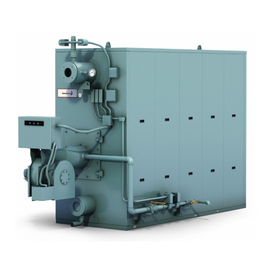
- Page 1 Table Of Contents $30.00 U.S. CLEAVER-BROOKS MODEL FLX PACKAGED BOILER Operation, Service, and Parts Manual 1,500,000 to 12,000,000 Btu/hr Hot Water and Steam Fuel: Light Oil, Gas or Combination Manual Part No. 750-177 r4 6/2001...
-
Page 2: Safety Precautions
SAFETY PRECAUTIONS AND Abbreviations ABBREVIATIONS Following is an explanation of the abbreviations, acronyms, and symbols used in this manual. Safety Precautions It is essential to read and understand the following safety Alternating Current precautions before attempting to operate the equipment. Failure to follow these precautions may result in damage to Automatic Reset equipment, serious personal injury, or death. - Page 3 MODEL FLX PACKAGED BOILER Operation, Service, and Parts Manual 1,500,000 to 12,000,000 Btu/hr Fuel: Light Oil, Gas or Combination Cleaver-Brooks 2001 Please direct purchase orders for replacement manuals to your local Cleaver-Brooks authorized representative Manual Part No. 750-177 R4 Revised 6/2001 Printed in U.S.A.
- Page 4 ! DANGER WARNING DO NOT OPERATE, SERVICE, OR REPAIR THIS EQUIPMENT UNLESS YOU FULLY UNDERSTAND ALL APPLICABLE SECTIONS OF THIS MANUAL. DO NOT ALLOW OTHERS TO OPERATE, SERVICE, OR REPAIR THIS EQUIPMENT UNLESS THEY FULLY UNDERSTAND ALL APPLICABLE SECTIONS OF THIS MANUAL. FAILURE TO FOLLOW ALL APPLICABLE WARNINGS AND INSTRUCTIONS MAY RESULT IN SEVERE PERSONAL INJURY OR DEATH.
-
Page 5: Table Of Contents
TABLE OF CONTENTS Chapter 1 Basics of Flexible Watertube Operation A. General ............... . 1-1 B. - Page 6 TABLE OF CONTENTS(continued) Chapter 5 Starting And Operating Instructions A. General Preparation for Initial Startup ..........5-1 B.
- Page 7 TABLE OF CONTENTS(continued) Chapter 8 Inspection And Maintenance A. General ............... . 8-1 B.
- Page 8 Notes...
-
Page 9: General
CHAPTER 1 GENERAL DESCRIPTION A. General ........1-1 B. -
Page 10: The Boiler
Chapter 1 GENERAL DESCRIPTION B. The Boiler The type of service that your boiler is required to provide has an important bearing on the amount of waterside care it will The Cleaver-Brooks Model FLX is a five-pass steel boiler require. with flexible watertubes formed and arranged so as to direct the flow of combustion gases through the boiler. - Page 11 GENERAL DESCRIPTION Chapter 1 Water Column Assembly (Figure 1-2): Houses the low- Modulating Limit Pressure Control (Figure 1-2 and 1-3): Senses changing boiler pressures and transmits the water cutoff and pump control and includes the water information to the modulating motor to change the gauge glass, gauge glass shutoff cocks.
-
Page 12: Hot Water Controls (All Fuels)
Chapter 1 GENERAL DESCRIPTION avoid overtightening, which can distort the seats. Use only flat-jawed wrenches on the flats provided. When installing a flange-connected valve, use a new gasket and draw the mounting bolts down evenly. Do not install or remove side outlet valves by using a pipe or wrench in the outlet. - Page 13 GENERAL DESCRIPTION Chapter 1 stop or start the burner at a preselected operating level in the boiler drops below the master low-water temperature. cutoff point. High Limit Temperature Control (Figure 1-7): Breaks a Safety Valve(s) (Figure 1-6 and 1-8): Prevent buildup circuit to stop burner operation on a rise of temperature over the design pressure of the pressure vessel.
- Page 14 Chapter 1 GENERAL DESCRIPTION S U P P O RT F R O M B U I L D I N G remove side outlet valves by using a pipe or wrench in C O N S T R U C T I O N DISCHARGE OPENING the outlet.
-
Page 15: Profire Burner Operation And Control
CHAPTER 2 ProFire Burner Operation and Control A. GENERAL ....... . 1 B. -
Page 16: Recommended Fuels And Ventilation
Chapter 2 ProFire Burner Operation and Control MODEL NO. 1000 1100 1200 15480 20640 25800 30960 36120 41280 46440 51600 56760 61920 72240 82560 92280 103200 113520 123840 (scfh) 1207 1609 2012 2414 2817 3219 3621 4024 4426 4828 5633 6438 7243 8048... - Page 17 ProFire Burner Operation and Control Chapter 2 the boiler operating controls indicate a demand for hot water or steam. • Burner Switch: Activates or deactivates the op- erating cycle of the flame safeguard control. • Manual Flame Control: When in Manual Mode, it provides manual adjustment of the burner fir- ing rate between low-fire and high-fire opera- tion.
- Page 18 Chapter 2 ProFire Burner Operation and Control 20. Airbox (Figure 2-6). The airbox is attached to the inlet side of providing air flow. The fuel supply valves will not open the fan housing. It serves as the inlet and flow regulating if this switch does not sense adequate air pressure.
- Page 19 ProFire Burner Operation and Control Chapter 2 ACCOMPLISHED ITEM REMARKS Daily Gauges, Monitors, Operator Make visual inspection and record readings in log. and Indicators Instrument and Operator Make visual check against recommended specifications. Equipment Settings Low-water Fuel Cut- Operator Refer to instructions. off And Alarm Weekly Low-water Fuel Cut-...
- Page 20 Chapter 2 ProFire Burner Operation and Control ACCOMPLISHED ITEM REMARKS Inspect Burner Service Technician Refer to instructions. Components Annually High Limit Safety Service Technician Manually adjust until switch opens. Control Firing Rate Control Service Technician Check with combustion test. Pilot and Main Gas Service Technician Perform leakage tests.
- Page 21 ProFire Burner Operation and Control Chapter 2 Special Tools The Impeller puller, part number 943-388 should be used to remove the impeller from the fan motor shaft. To order special tools, contact your authorized Cleaver-Brooks representative. Figure 2-8: Impeller Puller Part Number 943-388 750-177...
- Page 22 Chapter 2 ProFire Burner Operation and Control Notes: 750-177...
-
Page 23: Pressure Vessel Care
CHAPTER 3 Pressure Vessel Care A. General........3-1 B. -
Page 24: System Pressure
Chapter 3 Pressure Vessel Care DT = 20°F DT = 40°F DT = 60°F DT = 80°F DT = 100°F MODEL DP (PSIG) DP (PSIG) DP (PSIG) DP (PSIG) (PSIG) FLX-150 1.14 122.0 0.30 61.1 0.13 41.1 0.08 30.8 0.05 24.4 FLX-200 1.14... -
Page 25: Water Requirements (Steam Boilers)
Pressure Vessel Care Chapter 3 exercised to make sure that the proper relationship of pressure Multiple Boiler Installations to temperature exists within the boiler so that all of its internal When multiple boilers of equal or unequal size are installed, surfaces are fully wetted at all times. -
Page 26: Water Treatment
Chapter 3 Pressure Vessel Care BOILER MODEL 1000 1100 1200 Minimum Feed Rate (gpm) 11.6 13.2 14.9 16.5 18.2 19.8 23.1 26.4 29.7 33.0 36.3 39.6 Note: Feedwater to the boiler must be at least 60 °F, for minimum performance, 212 °F is preferred. Table 3-2: Minimum Boiler Feed Water Flow Rates (Steam Boiler) Because of the variables involved, no one “boiler compound”... - Page 27 Pressure Vessel Care Chapter 3 control system, in order to lower the concentration of solids ! DANGER CAUTION in the water. Solids are introduced to the boiler with the feedwater, even When initially opening the blowdown valve, though this water may be treated prior to use. These solids open the valve slowly to heat the discharge become less soluble when the water is heated and evaporated, piping.
-
Page 28: Cleaning
Chapter 3 Pressure Vessel Care F. CLEANING G. BOILOUT Although it may be necessary to clean the system, Any oil, grease, or other contamination found to be present on information in this chapter deals primarily with cleaning the waterside heating surfaces should be removed promptly by boiler under isolated conditions. - Page 29 Pressure Vessel Care Chapter 3 and wash all internal surfaces, including tubes. It may be 12. Throughout the entire process, each blow-down point or necessary to use a high pressure hose or a wash out lance valve should be blown at least once every two hours. The to flush out inaccessible areas.
-
Page 30: Washing Out
Chapter 3 Pressure Vessel Care H. WASHING OUT available. Be prepared to perform any testing required by the inspector, including a hydrostatic test. Depending on system integrity, feedwater quality, or When shutting down a boiler, the load should be reduced operating conditions, the water side of the boiler may need to gradually and the pressure vessel should be cooled at a rate be washed out on occasion. -
Page 31: Preparation For Extended Lay-Up
Pressure Vessel Care Chapter 3 Waterside Inspection Preparing The Boiler For Layup Check all water piping and valves for leaks, wear, corrosion, To prepare a boiler for layup, thoroughly clean the fireside by and other damage. Replace or repair the piping and valves as removing any soot or other products of combustion from the necessary. - Page 32 Chapter 3 Pressure Vessel Care possibility of freezing temperatures must be considered. ! DANGER WARNING Again, take care to protect metal surfaces. Because of the number of variables, it is difficult to offer definite recommendations. However, it is suggested that the pressure Materials described in this section may be vessel be drained, thoroughly cleaned internally, and refilled considered hazardous under the U.S.
-
Page 33: Sequence Of Operation
CHAPTER 4 Sequence Of Operation A. General ........4-1 B. -
Page 34: Sequence Of Operation - Oil Or Gas
Chapter 4 Sequence Of Operation C. SEQUENCE OF OPERATION - OIL Blower Motor Starter Circuit OR GAS • Blower motor starter (BMS) On a combination fuel unit, the gas/oil switch must be set for Running lnterlock Circuit the proper fuel. •... -
Page 35: Flame Loss Sequence
Sequence Of Operation Chapter 4 the pressure vessel metal and refractory to The pilot flame must be established and proven by the flame undesirable conditions. detector (FD) within a 10 second period in order for the ignition cycle to continue. If for any reason this does not The burner starting cycle is now complete. - Page 36 Chapter 4 Sequence Of Operation The blower motor will continue to operate. The flame failure Preventive maintenance and scheduled inspection of all light and the alarm bell (optional) are energized 10 seconds components should be followed. Periodic checking of the later.
- Page 37 Sequence Of Operation Chapter 4 MNEMONIC DESCRIPTION MNEMONIC DESCRIPTION Burner Switch Amber (Color Of Pilot Light) Boiler Selector Switch AAFL Atomizing Air Failure Light BWPM Booster Water Pump Motor AAFR Atomizing Air Failure Relay Booster Water Thermostat AAPL Atomizing Air Proven Light AAPS Atomizing Air Proving Switch CAFL...
- Page 38 Chapter 4 Sequence Of Operation MNEMONIC DESCRIPTION MNEMONIC DESCRIPTION FDJB Flame Detector Junction Box H/LWA High Low Water Alarm FDPS Flow Differential Pressure Switch High Limit Control Flame Failure Alarm HLFC High-Low Fire Control Flame Failure Light HLPC High Limit Pressure Control Flame Failure Relay HLTC High Limit Temperature Control...
- Page 39 Sequence Of Operation Chapter 4 MNEMONIC DESCRIPTION MNEMONIC DESCRIPTION LLPR Low Limit Pressure Relay No Flow Relay Lead Lag Relay NGHPV Natural Gas Housing Purge Valve LLTC Low Limit Temperature Control LLTR Low Limit Temperature Relay Outlet Damper Actuator LOPL Low Oil Pressure Light Outlet Damper Motor LOPR...
- Page 40 Chapter 4 Sequence Of Operation MNEMONIC DESCRIPTION MNEMONIC DESCRIPTION Power On Light STLWR Surge Tank Low Water Relay Pilot Oil Valve Pre-Purging Light (T.C.) Timed Closed Post Purge Relay (T.O.) Timed Open PPTD Post Purge Time Delay Terminal Block Program Relay Thermocouple Purge Ready Light Time Clock...
-
Page 41: Starting And Operating Instructions
CHAPTER 5 STARTING AND OPERATING INSTRUCTIONS A. General Preparation for Initial Startup ..5-1 B. Startup Procedures ......5-5 C. - Page 42 Chapter 5 STARTING AND OPERATING INSTRUCTIONS 2. C 1. F ONTROL ETTINGS TEAM UPPLY ATER Before initial startup, verify that all fuel connections are tight. Fuel supply lines should be securely connected, correctly See Chapter 6 for adjustment instructions for the following supported, and leak tested.
- Page 43 STARTING AND OPERATING INSTRUCTIONS Chapter 5 3. E LECTRICAL EQUIREMENTS ONNECTIONS ! DANGER WARNING OIL SOLENOID VALVES CLOSED Shut off and lock out all electrical power to the burner before performing any service or maintenance that requires removal of electrical equipment covers or component OIL CIRCULATION parts.
- Page 44 Chapter 5 STARTING AND OPERATING INSTRUCTIONS 5.01 - 12.00 MMBtu/hr N o t e : G a s t r a i n configurations are subject t o c h a n g e . T h e a b o v e c o n f i g u r a t i o n s r e f l e c t components at the date of t h i s...
-
Page 45: Startup Procedures
STARTING AND OPERATING INSTRUCTIONS Chapter 5 B. STARTUP PROCEDURES OIL PRESSURE GAUGE OIL TO BURNER PRESTART TASKS AND CHECKLIST - ALL FUELS OIL SOLENOID VALVES Before proceeding with system startup and adjustment, be sure that overall installation is complete. Review the boiler OIL BYPASS operating and installation manual set carefully to verify that TUBING... - Page 46 Chapter 5 STARTING AND OPERATING INSTRUCTIONS DIFFUSER OIL PIPE BAFFLE HIGH VOLTAGE IGNITER CABLE GAS ELECTRIC PILOT ASSEMBLY ITEM KEY SIZE 1 SIZE 2 SIZE 3 SIZE 4 Diffuser To B 1-11/16 2-1/4 3-1/8 3-1/8 DIFFUSER - TO - AIR BAFFLE Air Baffle ALIGNMENT DIMENSION CHOKE CONE...
-
Page 47: Burner Adjustments, Single Fuel Natural Gas
STARTING AND OPERATING INSTRUCTIONS Chapter 5 AIR AND FUEL CONTROLS Turndown capability for oil is less than that for natural gas. (DESCRIPTION) Therefore, on combination fueled burners, gas turndown performance may be restricted (or determined) by the excess The combustion system air and fuel controls have been air levels set initially for oil combustion. - Page 48 Chapter 5 STARTING AND OPERATING INSTRUCTIONS ProFire Packaged B urner System P res s. P res s . G as (CF H ) L iqu id (G P H ) ( In. WC ) (P S I) G az (P C H ) (Po.
- Page 49 STARTING AND OPERATING INSTRUCTIONS Chapter 5 NOTE: The linkages have been factory-set pressure indicated in Figure 5-10, and select the and tested, although they may require fine temporary firing rate. This rate for startup is not critical, adjustment for the specific application. If but merely an acceptable starting point to begin the high the linkage is not in place, or if the setting fire adjustment procedures.
- Page 50 Chapter 5 STARTING AND OPERATING INSTRUCTIONS INPUT RATE MMBtu/hr. DESCRIPTION 9.0 10.0 11.0 12.0 LINKAGE ARM ANGULAR ORIENTATION (IN DEGREES) Main Shaft Gas Valve Arm (Combination) Main Gas Valve Arm (Combination) Main Shaft Gas Valve Arm (Gas Only) Main Gas Valve Arm (Gas Only) Butterfly Valve Setting (Combination) Butterfly Valve Setting (Gas Only) ROD CLAMP POSITION FROM CENTER POINT (IN INCHES)
-
Page 51: Burner Adjustments, Single Fuel Oil Fired
STARTING AND OPERATING INSTRUCTIONS Chapter 5 13. Modulate the burner to low fire. The butterfly valve ! DANGER CAUTION should be adjusted to provide the correct fuel flow and pressure at the low-fire position in accordance with the This burner is designed to burn only those fuels burner data plate minimum gas-pressure rating. - Page 52 Chapter 5 STARTING AND OPERATING INSTRUCTIONS CONTROLS SETUP. Complete the following combination INPUT MINIMUM O MAXIMUM O system control setup steps before beginning the oil-fired (MMBtu/hr) burner startup procedure: SIZE 1 Check the linkages to confirm that they are securely fastened and ready for operation (see Figure 5-11).
- Page 53 STARTING AND OPERATING INSTRUCTIONS Chapter 5 Set the high-fire fuel input pressure to match the Size 4 burners utilize return flow nozzles rather than maximum oil pressure specification on the burner data simplex nozzlesused in smaller sizes. See Table 5-3 for plate by adjusting the fuel input.
-
Page 54: E. Burner Adjustments, Combination
Chapter 5 STARTING AND OPERATING INSTRUCTIONS 13. Check intermediate positions for proper combustion. Check the linkages to confirm that they are securely Adjust the linkage, as required, to match the fuel and air fastened and ready for operation (see Figures 3-2 and 3- rates indicated in Table 5-2. - Page 55 STARTING AND OPERATING INSTRUCTIONS Chapter 5 Place the manual flame potentiometer in the CLOSE After the system has been completely adjusted for oil- (low-fire) position. firing, place the burner switch to the off position, and position the fuel selector switch to GAS. Check the presetting of the air shutters.
- Page 56 Chapter 5 STARTING AND OPERATING INSTRUCTIONS 10. When the prepurge sequence ends, the pilot valve will tube) to determine an initial estimate of the gas input rate. open. The pilot flame should be visible from the viewing By doing so, and referring to Figure 5-10, an window.
- Page 57 STARTING AND OPERATING INSTRUCTIONS Chapter 5 NOTE: Some meters may require 6.0 IN. H small increments. This will cause the butterfly valve to c o r r e c t i o n t o P g a s . C o n s u l t m e t e r open farther, allowing more gas into the burner.
- Page 58 Chapter 5 STARTING AND OPERATING INSTRUCTIONS NOTE: It is unnecessary to readjust the The method for regulating the natural gas flow rate (manifold position of the high-fire or low-fire shutters pressure) is as follows: after having been set for oil firing. Maximum flow rate is established by operating the 16.
-
Page 59: Startup, Operating And Shutdown - All Fuels
STARTING AND OPERATING INSTRUCTIONS Chapter 5 The method for regulating the fuel-oil flow rate (nozzle ! DANGER WARNING pressure) is as follows: Maximum flow rate is established by operating the Do not re-light the pilot or attempt to start burner at high-fire with the oil metering valve in a nearly the main burner, either oil or gas, if the closed position with the modulating motor set at the combustion chamber is hot and/or if gas or... -
Page 60: Control, Operational Tests And Checks
Chapter 5 STARTING AND OPERATING INSTRUCTIONS position at other than low fire, the damper will not be in a strainers, foreign material in either new or closed position, thus allowing more air than desired to flow renovated fuel lines may lodge under a through the boiler. -
Page 61: Adjustment Procedures
CHAPTER 6 Adjustment Procedures A. General........6-1 L. -
Page 62: Modulating Motor
Chapter 6 Adjustment Procedures C. MODULATING MOTOR Initial adjustment should be made with the motor in full closed position, that is with the shaft on the power end of The modulating motor has a 90° shaft rotation. The motor the motor in its most counterclockwise position. manufacturer also provides a 160°... - Page 63 Adjustment Procedures Chapter 6 The Modulating Control senses changes in the hot water temperature or steam pressure and signals the modulating motor to control the flow of fuel and air to the burner. With either steam or hot water boilers, the modulating control must be set to ensure the burner is at its minimum low fire position before the operating limit control either starts or stops the burner.
- Page 64 Chapter 6 Adjustment Procedures 100% Modulation Control Response Firing Rate Operating Limit Control Response High Limit Control Safety Shutdown Minimum Input (Low Fire) Falling Temp. or Pressure Modulated Firing “ON - OFF” Range Differential Rising Temp. or Pressure Burner Off (Burner OFF) (Burner OFF) (Burner ON)
-
Page 65: Modulating Pressure Control (Steam)
Adjustment Procedures Chapter 6 utilization of the modulating firing system. To accomplish maximum utilization, and assuming that air/fuel combustion ratios have been set, make the required adjustments to the controls to bring the boiler pressure or temperature up to meet the load requirements. -
Page 66: Modulating Temperature Control (Hot Water)
Chapter 6 Adjustment Procedures K. HIGH LIMIT TEMPERATURE CONTROL (Hot Water) Set the “cut-out” (burner off) temperature on scale using the adjusting screw. The control will break the circuit and lock out on a rise in water temperature above the setting. The setting should be sufficiently above the operating limit temperature to avoid unnecessary shutdowns. -
Page 67: Gas Pressure And Flow Information
Adjustment Procedures Chapter 6 Although it is possible to visibly adjust the size of the pilot To express the volume obtained from an actual meter reading flame, it is preferable to obtain a microamp or voltage reading into cubic feet at base pressure, it is necessary to multiply the of the flame signal. - Page 68 Chapter 6 Adjustment Procedures ADJUSTMENT Using information from Section O of Chapter 6, determine the standard conditions of gas pressure and flow for the size After operating for a sufficient period of time to assure a boiler and the gas train on it. Calculate the actual pressure and warm boiler, adjustments should be made to obtain efficient flow through the use of correction factors that compensate for combustion.
-
Page 69: Low Gas Pressure Switch
Adjustment Procedures Chapter 6 MODEL NO. 1000 1100 1200 Fuel Consumption Gas (cfh) 1500 2000 2500 3000 3500 4000 4500 5000 5500 6000 7000 8000 9000 10000 11000 12000 A. Natural Gas @ 1000 Btu/cu-ft. Table 6-1: Hot Water and Steam Boiler Ratings REGULATOR INLET STD GAS MIN GAS... -
Page 70: Fuel Oil Combustion Adjustment
Chapter 6 Adjustment Procedures FIRST VISIBLE TRACE OF STACK HAZE PER CENT O IN FLUE GAS PER CENT CO 1/10 of 1% CO = 1,000 PPM PER CENT EXCESS AIR Figure 6-7: Flue Gas Analysis Chart for Natural Gas Because of variation in oils, including chemical content, source, blends, and viscosity characteristics, the temperatures and pressures listed in Chapter 5, and mentioned in the adjusting of the controls in the following paragraphs, will... -
Page 71: Low Oil Pressure Switch
Adjustment Procedures Chapter 6 U. LOW OIL PRESSURE SWITCH The L.O.P.S. prevents burner ignition, or stops its operation, when the oil pressure is below the setpoint. Adjust the control by turning the screw on top of control case to an indicated pressure 10 psi below the established primary oil pressure setting indicated on the oil supply pressure gauge. - Page 72 Chapter 6 Adjustment Procedures Notes 6-12 750-177...
-
Page 73: Troubleshooting
CHAPTER 7 Troubleshooting possibly eliminate overlooking an obvious condition, often ! DANGER WARNING one that is relatively simple to correct. If an obvious condition is not apparent, check the continuity Trouble shooting should be performed only of the circuits with a voltmeter or test lamp. Each circuit can by personnel who are familiar with the be checked and the fault isolated and corrected. - Page 74 Chapter 7 Troubleshooting SYMPTOM CAUSE ACTION NO IGNITION Electrode is grounded, porcelain is Replace. cracked. (LACK OF SPARK). Improperly Positioned Electrode Recheck Dimensions Loose connection between electrode and Reconnect or tighten. ignition transformer. Defective ignition transformer. Check transformer winding continuity. NO IGNITION Lack of fuel -- no gas pressure, closed fuel Check fuel supply and valves.
- Page 75 Troubleshooting Chapter 7 Problem Solution BURNER DOES NOT START No voltage at program relay power input terminals. A. Main disconnect switch open. B. Blown control circuit fuse. C. Loose or broken electrical connection. Program relay safety switch requires resetting. Limit circuit not completed—no voltage at end of limit circuit program relay terminal.
- Page 76 Chapter 7 Troubleshooting Problem Solution PILOT FLAME, BUT NO Insufficient pilot flame. MAIN FLAME Gas Fired Unit. A. Manual gas cock closed. B. Main gas valve inoperative. C. Gas pressure regulator inoperative. Oil fired unit. A. Oil supply cut off by obstruction, closed valve, or loss of suction. B.
- Page 77 Troubleshooting Chapter 7 Problem Solution SHUTDOWN OCCURS Improper air/fuel ratio (lean fire). DURING FIRING A. Slipping linkage. B. Damper stuck open. C. Fluctuating fuel supply. 1). Temporary obstruction in fuel line. 2). Temporary drop in gas pressure. Interlock device inoperative or defective. MODULATING MOTOR Manual-automatic switch in wrong position.
- Page 78 Chapter 7 Troubleshooting Problem Solution 2. Cold system startup. A. Any time a boiler is started with a cold system, it will produce condensate until ° internal surface temperatures exceed 130 F. Internal condensation will not be produced once a boiler has warmed up. Condensate will dry up after a short time. Limit number of cold starts.
-
Page 79: General
CHAPTER 8 Inspection and Maintenance A. General ........8-1 B. -
Page 80: Fireside Cleaning
Chapter 8 Inspection and Maintenance operator with an excellent opportunity to perform a detailed Tubes should be brushed with a wire brush to remove any check of all components of the boiler, including piping, soot or other accumulations. Refractory surfaces should be valves, pumps, gaskets, refractory, etc. - Page 81 Inspection and Maintenance Chapter 8 The flue outlet and stack should also be inspected annually Install gasket on side casing panels so it extends past the top and cleaned as necessary. Commercial firms are available to and bottom by 1/4" or more and 1/16" to 1/8" out the back at perform this work.
-
Page 82: Controls
Chapter 8 Inspection and Maintenance E. CONTROLS accordance with Section IV of the ASME Boiler and Pressure Vessel Code. Relief Valves Low Water Controls (Hot Water) The relief valve is a very important safety device and Most instances of major boiler damage result from operating deserves attention accordingly. - Page 83 Inspection and Maintenance Chapter 8 when the blow down valve is open allowing water to drain ! DANGER CAUTION from the control. The test-n-check valves permit testing of the control without draining the entire system therefore allowing regularly scheduled verification of float style low water If a control does not break the circuit to stop cutoff.
-
Page 84: Oil Burner Maintenance
Chapter 8 Inspection and Maintenance Electrical Controls Refer to the burner manual for information regarding tests of the flame safeguard system. Contact your local Cleaver- The operating controls should be inspected monthly. Brooks authorized representative for assistance, if required. Examine the tightness of electrical connections and keep the controls clean. -
Page 85: Gas Burner Maintenance
Inspection and Maintenance Chapter 8 G. GAS BURNER MAINTENANCE the condition of the refractory and insulation and will guard against unexpected downtime for repairs. Refer to the burner sections for specific information regarding operation and maintenance of the burner. The I. - Page 86 Chapter 8 Inspection and Maintenance Sight Port gasket. Start tightening at the top and proceed around the door, alternately tightening opposite fasteners until all are Inspect the area around the sight port for paint discoloration. snug. After the boiler is back in operation, check for gas leaks A hot spot around the rear sight port is caused by either a poor around the door opening, and retighten the fasteners as seal between the sight port insulator and the wall, a cracked...
-
Page 87: Profire Burner Parts
CHAPTER 9 Section 1: ProFire Burner Parts The following is a brief list of the burner components, which Cleaver Brooks may need replacement over the life of the burner, depending P r o F i r e D I V I S I O N O F A Q U A - C H E M M I L W A U K E E , W I S C O N S I N on the burner’s operating conditions and use. -
Page 88: Control Panel
CHAPTER 9 Section 1: ProFire Burner Parts CONTROL PANEL DOOR (FRONT VIEW) CONTROL PANEL DOOR (FRONT VIEW) FLAME FAILURE LOAD DEMAND BURNER SWITCH MANUAL FLAME MODULATING MODE FUEL VALVE LOW WATER FLAME FAILURELOAD DEMANDBURNER SWITCH MANUAL FLAME MODULATING MODE FUEL VALVE LOW WATER CONTROL MANUAL... - Page 89 Section 1: ProFire Burner Parts CHAPTER 9 ITEM DESCRIPTION PART # CABINET, 20W X 14H X 7D W/SUB-BASE 848-1128 CABINET, 25W X 14H X 7D W/SUB-BASE 848-1155 TERMINAL BLOCK, 30 TERMS 434-80 FUSE BLOCK 848-1147 FUSE 5.AMP 832-1811 GROUND LUG 884-78 NAMEPLATE 118-3135...
- Page 90 CHAPTER 9 Section 1: ProFire Burner Parts TABLE 9-1B. SIZING CHART SINGLE-PHASE THREE-PHASE MOTOR HP CONT OVER CONT OVER CONT OVER CONT OVER CONT OVER CONT OVER CODE LOAD CODE LOAD CODE LOAD CODE LOAD CODE LOAD CODE LOAD – –...
- Page 91 Section 1: ProFire Burner Parts CHAPTER 9 2 OR 4 1 OR 3 Gas Train Insurance Designation Burner Ratings Standard 1.5 - 2.5 MMBtu/hr 2.51 - 5.00 MMBtu/hr 5.01 - 12.00 MMBtu/hr PART NO. ITEM NO. DESCRIPTION 1 — 1/2” 2”...
- Page 92 CHAPTER 9 Section 1: ProFire Burner Parts Table 9-2A MAN. REG SET PRESS. STANDARD PRESS. (1 PSI MAX INLET) HIGH PRESS (10 PSI MAX INLET & ALL CANADA) INPUT PRESS. TRAIN 1 VALVE 2 VALVES 1 VALVE 2 VALVES SPRING 1 VALVE 2 VALVES SPRING...
- Page 93 Section 1: ProFire Burner Parts CHAPTER 9 Table 9-2A MAN. REG SET PRESS. STANDARD PRESS. (1 PSI MAX INLET) HIGH PRESS (10 PSI MAX INLET & ALL CANADA) INPUT PRESS. TRAIN 1 VALVE 2 VALVES 1 VALVE 2 VALVES SPRING 1 VALVE 2 VALVES SPRING...
- Page 94 CHAPTER 9 Section 1: ProFire Burner Parts ITEM DESCRIPTION SIZE 1 SIZE 2 SIZE 3 SIZE 4 PART NO. PART NO. PART NO. PART NO. OIL SHUT-OFF SOLENOID VALVE 948-320 948-320 948-319 948-319 OIL PRESSURE GAUGE 850-1247 850-1247 850-1247 850-1247 GAUGE ADAPTER BUSHING 847-1082 847-1082...
- Page 95 Section 1: ProFire Burner Parts CHAPTER 9 NOTE:Burner size is shown on the nameplate. If necessary, size can also be determined by measuring the oil gun nozzle and coupling length. (“B” figure 9-5) • Size 1 = 23.0 in. • Size 2 = 24.5 in. •...
- Page 96 CHAPTER 9 Section 1: ProFire Burner Parts MOTOR OPEN DRIP PROOF (O.D.P.) TOTALLY ENCLOSED (T.E.F.C.) 200/230/460 575/600 115/230 200/230/460 575/600 115/230 894-3580 894-3598 894-3590 * 894-3608 894-3626 894-3618 894-3581 894-3599 894-3591 * 894-3609 894-3627 894-3619 894-3582 894-3600 894-3592 * 894-3610 894-3628 894-3620 894-3583 *...
- Page 97 Section 1: ProFire Burner Parts CHAPTER 9 NOTE:Burner size is shown on the nameplate. If necessary, size can also be determined by measuring the oil gun nozzle and coupling length. (“B” figure 8-5) • Size 1 = 23.0 in. • Size 2 = 24.5 in. •...
- Page 98 CHAPTER 9 Section 1: ProFire Burner Parts NOTE:Burner size is shown on the nameplate. If necessary, size can also be determined by measuring the oil gun nozzle and coupling length. (“B” figure 8-5) • Size 1 = 23.0 in. • Size 2 = 24.5 in. •...
- Page 99 Section 1: ProFire Burner Parts CHAPTER 9 METERING VALVE OIL PUMP AIR PROVING CHOKE SWITCH CONE SIZES 3 & 4 OIL NOZZLE ORIFICE SPUDS AIR PROVING SWITCH SIZES 1 & 2 INPUT DEPENDENT ITEMS INPUT CHOKE ORIFICE OIL DRIVE COUPLING WEBSTER MMBtu CONE...
- Page 100 CHAPTER 9 Section 1: ProFire Burner Parts NOTES 9-14 750-177...
-
Page 101: Casing Parts
Casings Chapter 9 CHAPTER 9B Section 2: Casing Parts Page Number ASSEMBLY, CASING (250) H.W., FLEXTUBE 9-16 ASSEMBLY, CASING (250) STEAM, FLEXTUBE 9-18 ASSEMBLY, CASING (350) H.W., FLEXTUBE 9-20 ASSEMBLY, CASING (350) STEAM, FLEXTUBE 9-22 ASSEMBLY, CASING (500) H.W., FLEXTUBE 9-24 ASSEMBLY, CASING (500) STEAM, FLEXTUBE 9-26... - Page 102 Chapter 9 Casings TOP VIEW TYPICAL SIDE 41 , 37 RIGHT SIDE VIEW REAR VIEW 39 , 37 TYPICAL SIDE FRONT VIEW BASE ANGLE (REF) END WALL 42 , 43 TOP VIEW TYPICAL LOWER CORNER 26 , 27 TYPICAL INNER CASING JOINT 42 , 43 30, 45...
- Page 103 Casings Chapter 9 HOT WATER PART NO. ITEM REQ. DESCRIPTION 315-726 Base 315-731 Roof 315-732 Inner casing - center 315-733 Inner casing - right rear 315-734 Inner casing - right front 315-735 Inner casing - left rear 315-736 Inner casing - left front 315-737 Inner casing bolt angles-lower center 315-738...
- Page 104 Chapter 9 Casings TOP VIEW TYPICAL SIDE 41 37 RIGHT SIDE VIEW REAR VIEW FRONT VIEW TYPICAL SIDE BASE ANGLE (REF) END WALL 26 27 TYPICAL LOWER CORNER TOP VIEW TYPICAL INNER CASING JOINT 42 43 FRONT VIEW RIGHT SIDE VIEW ASSEMBLY, CASING (250) STEAM, FLEXTUBE 9-18 750-177...
- Page 105 Casings Chapter 9 STEAM PART NO. ITEM REQ. DESCRIPTION 315-726 Base 315-844 Roof 315-845 Inner casing - center 315-846 Inner casing - right rear 315-847 Inner casing - right front 315-848 Inner casing - left rear 315-849 Inner casing - left front 315-737 Inner casing bolt angles-lower center 315-738...
- Page 106 Chapter 9 Casings TOP VIEW TYPICAL SIDE 41 , 37 REAR VIEW RIGHT SIDE VIEW 39 , 37 TYPICAL SIDE FRONT VIEW BASE ANGLE (REF) 42 , 43 TYPICAL LOWER CORNER 26 , 27 TOP VIEW TYPICAL INNER CASING JOINT 42 , 43 30 , 45 FRONT VIEW...
- Page 107 Casings Chapter 9 HOT WATER PART NO. ITEM REQ. DESCRIPTION 315-727 Base 315-759 Roof 315-760 Inner casing - center 315-761 Inner casing - right rear 315-762 Inner casing - right front 315-763 Inner casing - left rear 315-764 Inner casing - left front 315-737 Inner casing bolt angles-lower center 315-765...
- Page 108 Chapter 9 Casings TOP VIEW TYPICAL SIDE 41 , 37 RIGHT SIDE VIEW REAR VIEW 39 , 37 TYPICAL SIDE FRONT VIEW BASE ANGLE (REF) END WALL 42,43 TOP VIEW 26, 27 TYPICAL LOWER CORNER TYPICAL INNER CASING JOINT 42, 43 46 45 FRONT VIEW RIGHT SIDE VIEW...
- Page 109 Casings Chapter 9 STEAM PART NO. ITEM REQ. DESCRIPTION 315-727 Base 315-861 Roof 315-862 Inner casing - center 315-863 Inner casing - right rear 315-864 Inner casing - right front 315-865 Inner casing - left rear 315-866 Inner casing - left front 315-737 Inner casing bolt angles-lower center 315-765...
- Page 110 Chapter 9 Casings TOP VIEW TYPICAL SIDE 3741 41 37 REAR VIEW RIGHT SIDE VIEW 39 37 FRONT VIEW TYPICAL SIDE BASE ANGLE (REF) END WALL 4243 TYPICAL LOWER CORNER 2627 TOP VIEW TYPICAL INNER CASING JOINT 11 3 30 45 FRONT VIEW RIGHT SIDE VIEW ASSEMBLY, CASING (500) H.W., FLEXTUBE...
- Page 111 Casings Chapter 9 HOT WATER PART NO. ITEM REQ. DESCRIPTION 315-728 Base 315-783 Roof 315-784 Inner casing - center 315-785 Inner casing - right rear 315-786 Inner casing - right front 315-787 Inner casing - left rear 315-788 Inner casing - left front 315-737 Inner casing bolt angles-lower center 315-789...
- Page 112 Chapter 9 Casings TOP VIEW TYPICAL SIDE REAR VIEW RIGHT SIDE VIEW FRONT VIEW TYPICAL SIDE BASE ANGLE (REF) END WALL TYPICAL LOWER CORNER 26 27 TOP VIEW TYPICAL INNER CASING 11 3 JOINT 46 45 FRONT VIEW RIGHT SIDE VIEW ASSEMBLY, CASING (500) STEAM, FLEXTUBE 9-26 750-177...
- Page 113 Casings Chapter 9 STEAM PART NO. ITEM REQ. DESCRIPTION 315-728 Base 315-878 Roof 315-879 Inner casing - center 315-880 Inner casing - right rear 315-881 Inner casing - right front 315-882 Inner casing - left rear 315-883 Inner casing - left front 315-737 Inner casing bolt angles-lower center 315-789...
- Page 114 Chapter 9 Casings TOP VIEW TYPICAL SIDE 41 37 REAR VIEW RIGHT SIDE VIEW FRONT VIEW TYPICAL SIDE BASE ANGLE (REF) END WALL TYPICAL LOWER CORNER 42 43 TOP VIEW 26 27 11 3 11 3 11 3 TYPICAL INNER CASING JOINT 30 45 RIGHT SIDE VIEW...
- Page 115 Casings Chapter 9 HOT WATER PART NO. ITEM REQ. DESCRIPTION 315-729 Base 315-806 Roof 315-807 Inner casing - center 315-808 Inner casing - right rear 315-809 Inner casing - right front 315-810 Inner casing - left rear 315-811 Inner casing - left front 315-737 Inner casing bolt angles-lower center 315-812...
- Page 116 Chapter 9 Casings TOP VIEW 22 44 TYPICAL SIDE 37 41 4137 RIGHT SIDE VIEW REAR VIEW 39 37 FRONT VIEW TYPICAL SIDE BASE ANGLE (REF) END WALL TYPICAL LOWER CORNER TOP VIEW 26 27 11 3 11 3 11 3 11 3 TYPICAL INNER CASING JOINT...
- Page 117 Casings Chapter 9 STEAM PART NO. ITEM REQ. DESCRIPTION 315-928 Base 315-895 Roof 315-896 Inner casing - center 315-897 Inner casing - right rear 315-898 Inner casing - right front 315-899 Inner casing - left rear 315-900 Inner casing - left front 315-901 Inner casing bolt angles-lower center 315-902...
- Page 118 Chapter 9 Casings TOP VIEW 22 44 TYPICAL SIDE 37 41 41 37 REAR VIEW RIGHT SIDE VIEW 39, 37 FRONT VIEW BASE ANGLE (REF) END WALL TYPICAL LOWER CORNER 42, 43 TOP VIEW 26 , 27 11 3 11 3 11 3 TYPICAL INNER CASING JOINT...
- Page 119 Casings Chapter 9 1100 HOT WATER PART NO. ITEM REQ. DESCRIPTION 315-730 Base 315-832 Roof 315-807 Inner casing - center 315-833 Inner casing - right rear 315-834 Inner casing - right front 315-835 Inner casing - left rear 315-836 Inner casing - left front 315-737 Inner casing bolt angles-lower center 315-837...
- Page 120 Chapter 9 Casings TOP VIEW 22 44 TYPICAL SIDE 37 41 41 37 39 37 RIGHT SIDE VIEW REAR VIEW FRONT VIEW TYPICAL SIDE BASE ANGLE (REF) END WALL TYPICAL LOWER CORNER TOP VIEW 26 27 11 3 11 3 11 3 11 3 11 3...
- Page 121 Casings Chapter 9 1100 STEAM PART NO. ITEM REQ. DESCRIPTION 315-929 Base 315-918 Roof 315-896 Inner casing - center 315-919 Inner casing - right rear 315-920 Inner casing - right front 315-921 Inner casing - left rear 315-922 Inner casing - left front 315-901 Inner casing bolt angles-lower center 315-923...
- Page 122 Chapter 9 Casings Notes 9-36 750-177...
- Page 123 CHAPTER 9 Section 3: Controls Pressure Controls ............9-38 Level Controls .
- Page 124 ITEM 150# DESCRIPTION CONTROL, PRESSURE,HIGH LIMIT MANUAL RESET 817-415 817-109 CONTROL, PRESSURE, OPERATING AUTO RESET 817-16 817-110 817-229 817-244 CONTROL, PRESSURE, MODULATING GAUGE, PRESSURE 850-243 850-122 825-31 825-31 COCK, 1/4" 859-81 859-81 ELBOW, 3/4" TEE, 3/4" 859-25 859-25 858-165 858-165 UNION, 3/4"...
-
Page 125: Controls
Controls Chapter 9 ITEM REQ. PART N0. DESCRIPTION CONTROL, LIQUID LEVEL, WARRICK 3E2B 817-740 817-1020 CONTROL, LIQUID LEVEL, WARRICK 3E3B ITEM REQ. PART N0. DESCRIPTION 817-2349 LOW WATER CUTOFF, MCM&M 750-T-120, AR 67-536 1/4" BRASS ROD X 4 1/8" LG. LOW WATER CUTOFF, MCM&M 750-MT-120, MR 859-267 CROSS, 2"... - Page 126 Chapter 9 Controls ITEM PART N0. DESCRIPTION MAX. D.P. SEE NOTE 2 McDONNELL & MILLER 63B LWCO CONTROL SEE NOTE 2 McDONNELL & MILLER 64B LWCO CONTROL SEE NOTE 2 McDONNELL & MILLER 150B LWCO CONTROL 150# SEE NOTE 2 MAGNETROL B24 LIQUID LEVEL CONTROL 250# MAGNETROL B29 LIQUID LEVEL CONTROL...
- Page 127 Controls Chapter 9 ITEM PART N0. DESCRIPTION MAX. D.P. SEE NOTE #2 McDONNELL & MILLER 63B LWCO CONTROL SEE NOTE #2 McDONNELL & MILLER 64B LWCO CONTROL McDONNELL & MILLER 150B LWCO CONTROL SEE NOTE #2 150# SEE NOTE #2 MAGNETROL B24 LIQUID LEVEL CONTROL 250# MAGNETROL B29 LIQUID LEVEL CONTROL...
- Page 128 Chapter 9 Controls USED ON ITEM PART NO. DESCRIPTION STANDARD 100-271 LOW WATER CUT-OFF W/PUMP CONTROL (CB271) 817-620 LOW WATER CUT-OFF W/FEEDVALVE CONTROL(McDM 193A) OPTIONAL 817-371 LOW WATER CUT-OFF W/FEEDER (McDM 247-2) OPTIONAL 817-2305 McDM #750-MR CONTROL BOX STANDARD 817-2351 PROBE FOR McDM #750 817-740 AUX.
- Page 129 Controls Chapter 9 " " DETAIL C - C " " DETAIL C - C L.W.C.O. CASTING MARK L.W.C.O. CASTING MARK 1st VISIBLE 1st VISIBLE 3-3/4" 6-1/2" 3-3/4" 4-1/2" 5-3/8" POINT 6-1/2" 7-1/4" BOILER 8-3/4" BOILER POINT VALVE CLOSE PUMP OFF VALVE OPEN PUMP ON "...
- Page 130 Chapter 9 Controls Page left blank intentionally 9-44 750-177...
- Page 131 Controls Chapter 9 USED ON ITEM PART NO. DESCRIPTION VESSEL SIZE 250/350/500 817-2411 LOW WATER CUT-OFF W/PUMP CONTROL(McDM 157S-RD-MD) LOW WATER CUT-OFF (McDM 157S-R) 817-2406 800/1100 817-620 LOW WATER CUT-OFF W/FEEDVALVE CONTROL(McDM 193A) OPTIONAL 817-163 LOW WATER CUT-OFF W/PUMP CONTROL (Mag. W25) OPTIONAL McDM #750-MR CONTROL BOX - A.L.W.C.O.
- Page 132 Chapter 9 Controls PROBE LENGTHS A.L.W.C.O. PUMP ON PUMP OFF H.W. SIZE "A" "B" "C" "D" "E" 13-3/4" 22-1/2" 14-1/4" 13-3/4" 22-1/2" 14-1/4" 13-3/4" 22-1/2" 14-1/4" 15-3/4" 21-3/4" 21" 16-1/4" 24-1/2" 15-3/4" 16-1/4" 1100 24-1/2" USED ON ITEM PART NO. DESCRIPTION VESSEL SIZE SET WATER GAUGE...
- Page 133 Controls Chapter 9 McDM 750(VESSEL SIZE 250,350,500 ) & WARRICK E-2/E-3 (DELETE ALL ALWCO PIPING ) C OF WATER COLUMN 19" 19" "A" REF. 1" SEE DETAIL A.L.W.C.O. HIGH WATER C-C " " L.W.C.O. FRONT VIEW A.L.W.C.O. M D. M. 150 & Mag. B24 250,350,500 VESSEL SIZE ONLY 1/2"...
- Page 134 Chapter 9 Controls " " DETAIL C - C L.W.C.O. CASTING MARK 1st VISIBLE 5" POINT 5-3/4" 6-1/2" BOILER 7-1/2" PUMP OFF PUMP ON " " DETAIL C - C L.W.C.O. CASTING MARK 1st VISIBLE 3-3/4" 6-1/2" 5-3/8" POINT BOILER 8-3/4"...
- Page 135 NOTES...
- Page 136 Performance Proven Worldwide e-mail: info@cleaver-brooks.com Web Address: http://www.cleaver-brooks.com...
Need help?
Do you have a question about the FLX 150 and is the answer not in the manual?
Questions and answers