
Related Manuals for CleaverBrooks FLE


Summary of Contents for CleaverBrooks FLE
- Page 1 Model FLE Field Erectable Flexible Watertube Boiler Assembly Instructions 750-192 07/09...
- Page 2 WARNING ! DANGER WARNING ! DANGER If the information in this manual is not fol- Improper installation, adjustment, service, or maintenance can cause equipment damage, lowed exactly, a fire or explosion may re- personal injury, or death. Refer to the Opera- sult causing property damage, personal tion and Maintenance manual provided with injury or loss of life.
- Page 3 ! DANGER WARNING ! DANGER WARNING The boiler and its individual shutoff valve The installation must conform to the re- must be disconnected from the gas sup- quirements of the authority having jurisdic- ply piping system during any pressure tion absence such testing of that system at test pressures in...
- Page 4 Notes...
- Page 5 CLEAVER-BROOKS Model FLE Field Erectable Flexible Watertube Boiler Assembly Instructions Cleaver-Brooks 2009 Please direct purchase orders for replacement manuals to your local Cleaver-Brooks authorized representative. Manual Part No. 750-192 Printed in U.S.A. 07/09...
- Page 6 WARNING ! DANGER DO NOT OPERATE, SERVICE, OR REPAIR THIS EQUIPMENT UNLESS YOU FULLY UNDERSTAND ALL APPLICABLE SECTIONS OF THIS MANUAL. DO NOT ALLOW OTHERS TO OPERATE, SERVICE, OR REPAIR THIS EQUIPMENT UNLESS THEY FULLY UNDERSTAND ALL APPLICABLE SECTIONS OF THIS MANUAL. FAILURE TO FOLLOW ALL APPLICABLE WARNINGS AND INSTRUCTIONS MAY RESULT IN SEVERE PERSONAL INJURY OR DEATH.
-
Page 7: Table Of Contents
11. Pressurized Leak Test ......2-16 CHAPTER 3 FLE Casing Assembly Procedures 1. Install Wetpack around Vent Tube ..... 3-8 2. - Page 8 viii...
-
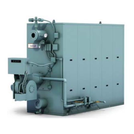
Page 9: The Boiler
1. The Boiler removable, formed steel panels. The fuel/air mixture The Cleaver-Brooks Model FLE Boiler is a field- from the burner combusts in the furnace area, then erectable, five-pass, steel boiler. Its flexible,... -
Page 10: Transportation And Handling
The total weight of each shipping crate handling should be done with an appropriately sized forklift or other suitable heavy lifting devices. Figure 1-2. Model FLE Boiler Tubes Being Readied to Ship Table 1-1: Boiler Components, Approximate Weights and Sizes PARTS... - Page 11 Table 1-1 cont’d PARTS HIGH PRESSURE STEAM LOW PRESSURE STEAM DESCRIPTION INFO 150-250 300-350 400-600 700-900 1000-1200 150-250 300-350 400-600 700-900 1000-1200 Base Assembly PART NO 315-1224 315-1169 315-1180 315-1194 315-1203 315-1224 315-1169 315-1180 315-1194 315-1203 (Insulated) APPROX. SIZE (in) 60x42 74x45-1/2 95x47-1/2...
-
Page 12: Order Of Assembly
Assembly of the boiler can be regarded as a four step process. The four steps are: Figure 1-3. ProFire burner mounted on a Model FLE 1. Pressure vessel assembly and boiler water side leak test (Chapter 2) 2. -
Page 13: Casing Assembly
Refer to the Dimension Diagram for fittings required. 5. Casing Assembly Figure 1-5. Model FLE (Hot Water) Installing the casing will require: • Front-end and rear-end walls and collar plates •... - Page 14 General Description Model FLE Assembly HIGH LIMIT PRESSURE CONTROL OPERATING LIMIT PRESSURE CONTROL MODULATION PRESSURE CONTROL PRESSURE GAUGE WATER COLUMN Figure 1-6. Typical Gas Train Figure 1-7. Trim Components (Hot Water) 750-192...
-
Page 15: Burner And Fuel Piping Installation
Model FLE Assembly General Description 6. Burner and Fuel Piping Installation Installing the burner requires: • Burner, • Gas and/or oil fuel delivery components, • Piping, and • Electrical conduit, fittings, etc. 7. Trim Installation Installing the trim components requires: •... - Page 16 General Description Model FLE Assembly 750-192...
-
Page 17: Preparation For Assembly
1. Preparation for Assembly properties of the ferrule joint and sealant. The Model FLE boiler uses eleven separate tube patterns that provide the gas passages for the five pass gas-flow configuration. One member of the assembly team should be designated to assure that the proper tube is selected for each tube position. - Page 18 Pressure Vessel Assembly Model FLE Assembly Figure 2-1. Completed Pressure Vessels; Steam (left) and Hot Water (right) Table 2- 1: Center-to-Center and Drum Length Dimensions Model Dimension (in) Drum Length End to Centerline to Centerline Steam Hot Water Steam Hot Water...
-
Page 19: Position The Base
Model FLE Assembly Pressure Vessel Assembly 2. Position the Base 3 layers of insulation under lower drum, front and rear Figure 2-2. Placing lower drum on base Figure 2-3. Front (left) and Rear (right) of the base Move the base into position with lifting straps, pry bars and winching equipment. -
Page 20: Upper Drum Placement
Pressure Vessel Assembly Model FLE Assembly 5. Upper Drum Placement Studs If there are any threads causing the tube retainer Using appropriately sized lifting devices, place the studs to bind, chase them with a 5/8” die (Figure 2- upper drum in position above the downcomer and 8). - Page 21 Model FLE Assembly Pressure Vessel Assembly The pressure vessel is assembled in the factory, hydro tested and stamped (Figure 2-9). For convenient assembly, prior to disassembly and crating, all the tubes are color coded and numbered with the corresponding numbers on the drums. In...
-
Page 22: Tube Installation
Pressure Vessel Assembly Model FLE Assembly 7. Tube Installation Tube installation should begin at the rear of the pressure vessel, in order to take advantage of the Tubes are formed in eleven different patterns in rigidity provided by the downcomer pipe. The... - Page 23 Model FLE Assembly Pressure Vessel Assembly Use a modified vice-grip clamp to secure the driving To achieve a tight fit between tubes, drive the tubes tool to the ferrule. to a uniform depth. Install the remaining tubes on the right side, follow-...
- Page 24 Pressure Vessel Assembly Model FLE Assembly Figure 2-13. Both ends of the tube must be inserted prior to driving the tubes Figure 2-15. Tubes driven to uniform depth Figure 2-14. Use a modified vice-grip to hold driving tool tight to the tube Figure 2-16.
- Page 25 TUBE PATTERNS, STEAM BOILER SIZE 150-250 300-350 400-600 700-1200 P/N TUBE # 1 93-3200 93-3211 93-3222 93-3233 P/N TUBE # 2 93-3201 93-3212 93-3223 93-3234 P/N TUBE # 3 93-3202 93-3213 93-3224 93-3235 P/N TUBE # 4 93-3203 93-3214 93-3225 93-3236 P/N TUBE # 5 93-3204...
- Page 26 TUBE PATTERNS, HOT WATER BOILER SIZE 150-250 300-350 400-600 700-1200 P/N TUBE #1 93-2685 93-2696 93-2707 93-2718 P/N TUBE #2 93-2686 93-2697 93-2708 93-2719 P/N TUBE #3 93-2687 93-2698 93-2709 93-2720 P/N TUBE #4 93-2688 93-2699 93-2710 93-2721 P/N TUBE #5 93-2689 93-2700 93-2711...
- Page 27 STEAM Boiler Sizes 150-250 300-350 400-600 Assembly Part No. 93-3244 93-3245 93-3246 ITEM DESCRIPTION PART NO PART NO PART NO TUBE PATTERN, NO. 1 93-3200 93-9211 93-3222 TUBE PATTERN, NO. 2 93-3201 93-9212 93-3223 TUBE PATTERN, NO. 3 93-3202 93-9213 93-3224 TUBE PATTERN, NO.
- Page 28 STEAM Boiler Sizes 700-900 Assembly Part No. 93-3247 ITEM DESCRIPTION PART NO TUBE PATTERN, NO. 1 93-3233 TUBE PATTERN, NO. 2 93-3234 TUBE PATTERN, NO. 3 93-3235 TUBE PATTERN, NO. 4 93-3236 TUBE PATTERN, NO. 5 93-3237 TUBE PATTERN, NO. 6 93-3238 TUBE PATTERN, NO.
- Page 29 STEAM Boiler Sizes 1000-1200 Assembly Part No. 93-3598 ITEM DESCRIPTION PART NO TUBE PATTERN, NO. 1 93-3233 TUBE PATTERN, NO. 2 93-3234 TUBE PATTERN, NO. 3 93-3235 TUBE PATTERN, NO. 4 93-3236 TUBE PATTERN, NO. 5 93-3237 TUBE PATTERN, NO. 6 93-3238 TUBE PATTERN, NO.
-
Page 30: Ferrule Retainers
Pressure Vessel Assembly Model FLE Assembly CAUTION - Ferrule Retainers must be installed as the tubes are being inserted. Failure to do so can lead to the tubes popping out. Figure 2-22. Ferrules must be driven in to expose only 3/4 inch of the tapered portion of the ferrule 8. -
Page 31: Pass Seals
Figures 2-19, 2-20 and 2-21. CAUTION Model FLE boilers are equipped with two lifting lugs located on the upper drum. The lugs should be used to lift or to pull the boiler. If the vessel is a Hot Water unit, be sure the front spreader is securely bolted in place prior Figure 2-28. -
Page 32: Installation Of Pressure Vessel To Base
CAUTION Before resealing WARNING - The assembled Model FLE ferrules, relieve pressure from the vessel. pressure vessel is heavy. Until the pressure Once the ferrules are resealed, repeat the vessel is secured to the base, it will be pressurized leak test. - Page 33 PTFE gasket material. In addition to applying the gasket, a small amount of Teflon paste and high temperature sealant, supplied with the Model FLE assembly kit, is to be applied to the indicated areas before the panels are installed.
- Page 34 Figure 3-1. Typical Hot Water Flextube Casing...
- Page 35 Part List, Hot Water 1100 ITEM DESCRIPTION PART # PART # PART # PART # PART # Base 315-1124 315-1169 315-1180 315-1194 315-1203 Roof 315-1127 315-1167 315-1178 315-1192 315-1202 Front wall, w/o Hinge 315-1262 315-1265 Front wall w Hinge 315-1128 315-1166 315-1177 315-1191...
- Page 36 Figure 3-2. Typical Low Pressure Steam Flextube Casing...
- Page 37 Part List, LP Steam 1100 PART PART PART ITEM DESCRIPTION PART # PART NO. Base 315-1124 315-1169 315-1180 315-1194 315-1203 Roof 315-1215 315-1230 315-1239 315-1250 315-1260 Front wall, w/o Hinge 315-1263 315-1264 Front wall w Hinge 315-1216 315-1229 315-1138 315-1249 315-1249 Rear wall-large piece 315-1217...
- Page 38 Figure 3-3. Typical High Pressure Steam Flextube Casing...
- Page 39 Parts List, HP Steam 1100 ITEM DESCRIPTION PART # PART # PART # PART # PART # Base 315-1124 315-1169 315-1180 315-1194 315-1203 Roof 315-1215 315-1230 315-1239 315-1250 315-1260 Front wall w/o Hinge 315-1263 315-1264 Front wall w Hinge 315-1216 315-1229 315-1238 315-1249...
-
Page 40: Install Wetpack Around Vent Tube
Casing Assembly Model FLE Assembly 1. Install Wetpack around Vent Tube • Position a length of wetpack over the internal portion of the tube to determine its length. Cut it to fit the tube then cut a 4” slit at the bottom. Tightly wrap the tube with the wetpack and tape (with masking or duct tape) it in place, leaving the slit at the bottom. -
Page 41: Install Rear Wall Sections
Model FLE Assembly Casing Assembly Lower Backing Plate • Install the retaining ring segments on the base around the lower drum. (Figure 3-9). Figure 3-8. Installing Backing Plate on Upper Drum 3. Install Rear Wall Sections • Check that there is gasket positioned on the bottom of the wall. - Page 42 Casing Assembly Model FLE Assembly 1. Install and snug up the long center bolts on both sides of the drum. Insert the pry bar on top of the drum to lift the wall fractionally while tightening the bolts, as this will prevent the gasket from tearing.
- Page 43 Model FLE Assembly Casing Assembly 4. With bar clamps, clamp the walls together at the cor- ners of the wall and clamp the entire wall to the base of the boiler (Figure 3-15). 5. Make sure that the walls are flush with each other and secure all of the bolts.
-
Page 44: Drill Rear Sight Port
Use the guide pipe as an applicator and add rigidizer solution (part# 872-00458, not included in FLE boiler assembly) to the outside of the pipe and apply it to the inside diameter of the hole in the insulation. - Page 45 Model FLE Assembly Casing Assembly 4. Insert the pipe from outside the boiler and direct it to the top of the tape measure (Figure 3-22). 5. Clean up any loose insulation from outside and inside the boiler. 6. Inspect the rear wall from inside the boiler. Push together any open seams in the Pyrobloc insulation and tap down the area.
-
Page 46: Finish Installing Backing Plates
Casing Assembly Model FLE Assembly 5. Finishing the Wetpack Installation Around the Lower Drum • Unfold the wetpack to cover the lower drum and tubes. Cover the entire base drum, overlapping adjoining wetpack rolls. Continue to mold the wet- pack around the lower drum and tube sections to prevent the plates from coming apart while packing the insulation (Figure 3-24). - Page 47 Model FLE Assembly Casing Assembly • In the roof, cut the hole for the front lift lug. This hole should be cut on about a 45º angle. • Position the roof to attach the front first. Attach two washers and one nut to every bolt, level the front, ensure the walls are flush with the edges of the roof and tighten the bolts.
-
Page 48: Install Burner Door
Casing Assembly Model FLE Assembly 9. Install Burner Door • Trim the insulation on the inside of the boiler at a 45º angle (Figure 3-32). • Pack any gaps in the insulation. • Using spray adhesive, install the rope gasket on the front wall inside the bolt pattern. -
Page 49: Install Lift Lug Cover
Model FLE Assembly Casing Assembly 10. Install Lift Lug Cover • Using the insulation trimmed from step 8 (part 4), fill the gap between the lift lug and the insulation. • Pack any gaps in the insulation (Figure 3-34). •... -
Page 50: Install Drum Packing And Seal Plates
Casing Assembly Model FLE Assembly 11. Install Drum Packing and Seal Plates Pack LDS moldable insulation (872-680) • around the upper and lower, front and rear drums to fill the void. Push it in toward the backing plate, compressing the insulation tightly. -
Page 51: Install Insulation Under Tubes
Model FLE Assembly Casing Assembly 12. Install Insulation Under Tubes • Install pyro-log insulation blocks (872-911) in the pass openings near the rear and in the gap left by the tubes at the bottom (Figure 3-42). The insulation blocks should be compressed together slightly and should be installed flush with the outside of the tubes. -
Page 52: Prepare For Inner Casing Installation
Casing Assembly Model FLE Assembly 14. Prepare for Inner Casing Installa- tion • Using a box cutter, trim any gasket that shows through the sides at the top of the front and back sections. Clean the area. Wipe off the sealing surface (the inside edge of the rear, and front walls, the roof and the base) and remove any lumps (Figure 3-46). - Page 53 Model FLE Assembly Casing Assembly 15. Prepare the Inner Casing Panels for Installation • Pack the insulation on the panels. It should be pushed from the top and bottom of the panel while tapping the insulation into the panel. After this is fin- ished, check that there are no holes between the insulation and the panel (Figure 3-51).
-
Page 54: Install Inner Casing
Casing Assembly Model FLE Assembly 14. Install Inner Casing NOTE: DO NOT touch the insulation when you are moving the panels. This can cause the insulation to move and undo the work from step 13. Try not to let the insulation touch the boiler until it is in its resting position (Figure 3-56). -
Page 55: Install Outer Casing
Model FLE Assembly Casing Assembly 17. Install Outer Casing • Stick the approximately 2” square pieced of insula- tion on the inner casing. Each panel will receive two pieces, one at the top and another in the middle near the bottom. See the drawings for placement loca- tions. - Page 56 Casing Assembly Model FLE Assembly 3-24 750-192...
-
Page 57: Burner Assembly, Gas Train, And Boiler Controls Installation
4. Electrical Connections and Layout ..4-3 and using a soapy water solution, either spray or brush the solution on all connections. If bubbles are The burner used to fire the Model FLE series boiler evident, suspected... - Page 58 Figure 4-2. Fuel Train Components...
-
Page 59: Electrical Connections And Layout
4. Electrical Connections and Layout The electrical connections and routing should follow the illustrations in this manual. Conduit, wiring and connections are supplied for the layout described. Deviation from the recommended wiring layout could result in a shortage of required material. Use the wiring diagram supplied with the boiler in conjunction with the illustrations in this manual for layout and wiring purposes. - Page 60 Figure 4-5. Typical conduit layout - ProFire burner on a hot water Flextube boiler...
- Page 61 Figure 4-6. Typical conduit layout - ProFire burner on a steam Flextube boiler...
- Page 62 Figure 4-7. Nameplate locations, hot water boiler...
- Page 63 Figure 4-8. Nameplate locations, steam boiler...
- Page 64 Web Address: http://www.cleaverbrooks.com...
Need help?
Do you have a question about the FLE and is the answer not in the manual?
Questions and answers