Table of Contents
Advertisement
Quick Links
Thank you for choosing the Wattage Cub 400EP ARF. Whether you have built and flown other electric
airplanes in the past, or if this is your first, you will appreciate the high quality, easy final assembly and
excellent flight characteristics of the Cub 400EP.
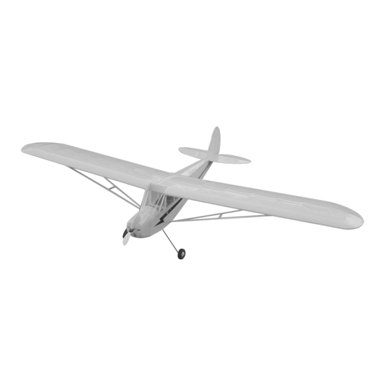
The Cub 400EP is a small electric-powered airplane built specifically for direct drive Speed 400 motors and
micro servos. The entire airframe is built up from lightweight balsa and plywood and covered with heat shrink
polyester covering material. This results in an airplane that is light, yet durable. And because of its light
weight, performance using a standard Speed 400 motor is excellent. The airplane is slow and stable throughout
the entire speed range, making it a perfect choice for beginner fliers. More experienced fliers will enjoy the Cub
400's semi-scale outline and good performance.
When you open the box, you will notice that you won't have much left to do or to purchase to finish your
new airplane. Included is all of the hardware necessary to finish the kit, including: prebent wire pushrods,
control horns, landing gear wires, wheels, molded cowl, molded windshield and color decals.
We hope you enjoy your new Wattage Cub 400EP ARF as much as we have enjoyed designing and building
it for you. If you have any questions or comments, please feel free to contact us. We have also included a
product survey in the back of this manual. After you have finished building the Cub 400EP, please take a few
minutes to fill it out and send it to us. We enjoy hearing any comments or suggestions that you may have.
The Wattage Cub 400EP ARF is distributed exclusively by Global Hobby Distributors
All contents copyright © 2000, Global Hobby Distributors Version V1.0 11/00
18480 Bandilier Circle, Fountain Valley, CA 92728
Advertisement
Table of Contents

Subscribe to Our Youtube Channel
Related Manuals for WattAge Cub 400EP


Summary of Contents for WattAge Cub 400EP
- Page 1 If you have any questions or comments, please feel free to contact us. We have also included a product survey in the back of this manual. After you have finished building the Cub 400EP, please take a few minutes to fill it out and send it to us.
-
Page 2: Table Of Contents
Applying the Decals ..........23 Control Surface Hinging ..........13 Balancing ..............23 Hinging the Elevator ..........13 Balancing the Cub 400EP ........23 Installing the Tail Wheel Assembly ...... 14 Control Throws ............24 Hinging the Rudder ..........14 Preflight Check............. -
Page 3: A Note About Covering
This instruction manual is designed to guide you through the entire final assembly process of your new Wattage Cub 400EP ARF in the least amount of time possible. Along the way you will learn how to properly assemble your new airplane and also learn many tips that will help you in the future. We have listed some of our recommenda- tions below. -
Page 4: Our Recommendations
The following section describes our recommendations to help you in deciding which types of accessories to purchase for your new Wattage Cub 400EP ARF. We have tested all of these items with the airplane and found that these products will offer the best in performance, reliability and economy. -
Page 5: Additional Items Required
We suggest using a 6 volt 380 - 480 size electric motor. For standard flying the Wattage Speed 400 motor shown would be a good choice. If you want to upgrade to a higher perfor- mance motor, the Multiplex Turbo 450 (# 239036) would be a good choice. -
Page 6: Full Size Hardware Drawings
1/8" Drill Bit Shown below are full size drawings of the small hardware parts included with the Cub 400EP ARF. Use these drawings to familiarize yourself with each part. Please refer back to this page to locate the proper parts when they are needed for a particular assembly step. -
Page 7: Kit Contents
We have organized the parts as they come out of the box for easier identification during assembly. Each photo below represents the parts that are required in a main section of the assembly process. Before you begin assembly, group the parts like we show. -
Page 8: Tools & Supplies Required
{1} Plywood Dihedral Brace (W-25) {1} Molded Plastic Cowling {2} 3mm x 25mm Machine Screws {1} Molded Clear Windshield {2} 3mm Flat Washers {1} Decal Set - not pictured {2} 3mm Blind Nuts {3} 2mm x 6mm Wood Screws {4} 25mm x 30mm Hook & Loop Material 2) Lay the motor, flight battery, charger, radio sys- tem and electronic speed control onto your work table. -
Page 9: Wing Assembly
8) Carefully spray a couple of light sprays of Per- trim and remove the excess covering from both of the root formance Plus Motor Spray inside the motor openings and ribs, leaving about 1/16" of material overlapping so it does apply a small drop of Trinity Break-In Drops onto each of not pull away later. -
Page 10: Joining The Wing Halves
5) Look carefully at the center section joint: the hold the two wing halves aligned until the epoxy fully wing halves should fit together tight with little or no gaps cures - about 1 hour. in the joint. See photo # 6 below. 13) Once the epoxy has fully cured, double-check Photo # 6 the center section joint. -
Page 11: Installing The Blind Nuts
5) While holding the wing in alignment, use a 10) After the blind nuts are fully seated, carefully couple of pieces of masking tape to hold the wing securely apply a thin layer of Kwik Bond Thin C/A around the to the fuselage. -
Page 12: Mounting The Horizontal Stabilizer
place a mark. Using a builder's triangle, extend this mark 8) When you are satisfied with the alignment, hold from front to back across the top of the stabilizer. See the stabilizer firmly in place using a couple of pieces of photo # 10 below. -
Page 13: Vertical Stabilizer
6) Slide the vertical stabilizer back into place and realign it. Using a builder's triangle, check to ensure that ITEMS REQUIRED the vertical stabilizer is aligned 90º to the horizontal sta- bilizer. See figure # 5 below. {1} Vertical Stabilizer w/Rudder & Hinges Figure # 5 TOOLS AND SUPPLIES REQUIRED Kwik Bond 5 Minute Epoxy... -
Page 14: Installing The Tail Wheel Assembly
the slots so that the centerline of the hinges are flush with 9) Test fit the tail wheel wire into the hole and the leading edge. If the hinges cannot be inserted deeply groove. When properly aligned, the wire should rest enough, use a modeling knife to carefully cut the hinge within the groove and the outer surface of the wire should slots deeper. -
Page 15: Main Landing Gear
16) With each of the hinges centered, apply 3-4 drops of Kwik Bond Thin C/A to the joint where the hinges 3) The two landing gear wires are held in place us- and the rudder meet. Allow a few seconds between drops ing two nylon landing gear straps and four 2mm x 10mm for the C/A to wick into the hinges, then turn the rudder wood screws. -
Page 16: Cowling Installation
1) Place the two short motor clamps onto the tops of the two hardwood mounting rails. The center of the ITEMS REQUIRED forward clamp should be 5/16" behind the front of the rails and the center of the rear clamp should be 1" behind {1} Molded Plastic Cowling the front of the rails. -
Page 17: Servo Installation
5) Using a pen, carefully mark the locations of the Figure # 7 three cowl mounting screws onto the cowling. One screw is located on the top, centerline of the cowl. The other two are located (one on each side) even with the hard- wood motor mount beams. -
Page 18: Installing The Rudder Control Horn
tighten both machine screws to draw the backplate into place. Be careful not to overtighten the screws. You don't want to crush the wood. See photo # 25 below. 1) Insert the Z-bend in the 1.5mm x 385mm push- Photo # 25 rod wire, into the third hole out from the base of the nylon control horn. -
Page 19: Installing The Servo Horn
22) Push right completely on the rudder control stick. While holding the control stick fully right, use a Before starting the next few steps, please make sure ruler and measure the amount the trailing edge of the rud- you have read and completely understood how your radio der moves right. -
Page 20: Installing The Servo Connector
control horn. Orientate the pushrod wire so that the longer two screws. Using a # 1 phillips screwdriver, evenly portion of the wire is on the right side of the control horn. tighten both machine screws to draw the backplate into See photo # 28 below. -
Page 21: Installing The Servo Horn
elevator moves up. This measurement should be 3/8" and should be taken at the widest point of the elevator. See 13) Per your radio system guide and ESC instruc- figure # 11 below. tions, plug the flight battery into the ESC, then plug the Figure # 11 ESC lead and the elevator servo lead into their proper slots in the receiver. -
Page 22: Aligning The Windshield
2) Set the windshield on the fuselage and push it 1) Using a modeling knife, remove the covering firmly into position. Use a couple of pieces of masking from over the two precut air-exit holes. The two holes tape to hold only the top of the windshield in place for are located in the bottom of the fuselage, 3-1/2"... -
Page 23: Installing The Wing Struts
9) After you've installed the lower ends of the struts, slide the metal pins in the upper ends of the struts into the The Cub 400EP should be balanced upright with the preinstalled nylon tubes in the bottom of the wing. See flight battery securely mounted in the fuselage. -
Page 24: Control Throws
NiCD's, or replaced if they are non-rechargeable cells and the voltage indicator drops out of the green. 5) Check every bolt and glue joint in the Cub 400EP to ensure that everything is tight and well-bonded. 6) Double check the balance of the airplane. Do this with the flight battery securely mounted in the fuselage. -
Page 25: Abc's Of Flying
Since you've chosen the Cub 400EP, you've avoided thrust. This is how the airplane flies when the motor is the most common mistake beginners make: choosing a turned off. - Page 26 Choosing the Cub 400EP greatly simplifies these ac- apply up elevator. Up elevator will maintain the plane's tivities. First, it takes very little thrust to overcome the altitude and will hold the airplane in the turn. To prevent drag: the airplane will actually glide without any motor the airplane from turning too steeply, as soon as a good power at all.
-
Page 27: Glossary Of Terms
The Cub 400EP uses heat The radio control system is proportional, meaning the sensitive polyester covering. -
Page 28: Notes
Motor Controller: Usually called an electronic speed Wing Hold Down Dowel: A length of hardwood dowel inserted through the fuselage at the front and back of the control (ESC), the motor controller controls the speed of wing. It is an anchor for the rubber bands that hold the the motor. -
Page 31: Product Evaluation Sheet
Simply fold this form on the dotted lines, seal with tape and mail it to us. Do not use staples and make sure our address faces out. 1) Kit: Cub 400EP ARF 7) Was any of the assembly difficult for you? If yes, please explain. - Page 32 Post Office ___________________________ will not ___________________________ deliver without ___________________________ proper (Return Address Here) postage Global Hobby Distributors Attn: Wattage Customer Care 18480 Bandilier Circle Fountain Valley CA 92728-8610 Fold along dotted line...
Need help?
Do you have a question about the Cub 400EP and is the answer not in the manual?
Questions and answers