Table of Contents
Advertisement
WARNING:
If the information in these instructions is not followed exactly, a fire or
explosion may result causing property damage, personal injury or loss of
life.
-
Do not store or use gasoline or other flammable vapors and liquids in the vicinity of this
or any other appliance.
WHAT TO DO IF YOU SMELL GAS
• Do not try to light any appliance.
• Do not touch any electrical switch; do not use any phone in your building.
• Immediately call gas supplier from a neighbor's phone. Follow the gas supplier's
instructions.
• If you cannot reach your gas supplier, call the fire department.
-
Installation and service must be performed by a qualified installer, service agency or the gas
supplier.
This appliance may be installed in
an aftermarket permanently
located, manufactured home (USA
only) or mobile home, where not
prohibited by local codes.
This appliance is only for use
with the type(s) of gas indicated
on the rating plate. A conversion
kit is supplied with the appliance.
Installation Manual
Installer:
After installation give this manual to the home-
owner and explain operation of this heater.
Copyright 2014, T.I.
$10.00
100-01347
- 864 TRV GSR2 -
Fireplace
Tested and Listed by
Report # B0516PRT-001
ANSI Z21.88
Built-In Direct Vent Fireplace
Natural Gas or Propane
Residential or Mobile Home
www.travisproducts.com
4140220
12521 Harbour Reach Drive
Mukilteo, WA 98275
Advertisement
Table of Contents

Subscribe to Our Youtube Channel
Related Manuals for Intertek 864 TRV GSR2


Summary of Contents for Intertek 864 TRV GSR2
- Page 1 - 864 TRV GSR2 - Fireplace Tested and Listed by Report # B0516PRT-001 ANSI Z21.88 Built-In Direct Vent Fireplace Natural Gas or Propane Residential or Mobile Home WARNING: If the information in these instructions is not followed exactly, a fire or explosion may result causing property damage, personal injury or loss of life.
-
Page 2: Overview
864 TRV GSR2 Owner's Manual (part # 100-01348). Listing Details This appliance was listed by Intertek Test Labs to ANSI Z21.88. The listing label is attached to the appliance near the gas control valve. A copy is shown to the right. -
Page 3: Table Of Contents
Table of Contents Table of Contents Overview ..............2 Top Vent Configuration with Vertical Termination ............29 Listing Details ............2 Termination Requirements ......... 30 Installation Options ..........6 Hearth Requirements .......... 31 Heating Specifications ......... 6 ... -
Page 4: Safety Warnings
Safety Precautions Safety Warnings Failure to follow all of the requirements may result in property damage, bodily injury, or even death. This unit must be installed by a qualified installer to prevent the possibility of an explosion. This appliance must be installed in accordance with all local codes, if any;... - Page 5 Safety Precautions Safety Warnings (continued) Allow the heater to cool before carrying out any maintenance or cleaning. Operate the heater according to the instructions included in this manual. If the main burners do not start correctly turn the gas off and call your dealer for service. ...
-
Page 6: Installation Options
Features and Specifications Installation Options Residential or Mobile Home Internal or External Chase Straight or Corner Placement Horizontal or Vertical Vent Flush or Recessed Face Bedroom Approved Raised or Floor Placement Heating Specifications Natural Gas Propane Approximate Heating Capacity (in square feet)*... -
Page 7: Packing List
Installation (for qualified installers only) Packing List Propane Conversion Kit Firestop (sku 93006094) Log Set Remote Control Additional Items Required Direct Vent Gas Line Equipment (shutoff valve, pipe, etc.) Electrical Equipment (min. 14 gauge, grounded line) Installation Overview ... -
Page 8: Massachusetts Requirements
Installation (for qualified installers only) Massachusetts Requirements NOTE: The following requirements reference various Massachusetts and national codes not contained in this document. Requirements for the Commonwealth of Massachusetts For all side wall horizontally vented gas fueled equipment installed in every dwelling, building or structure used in whole or in part for residential purposes, including those owned or operated by the Commonwealth and where the side wall exhaust vent termination is less than seven (7) feet above finished grade in the area of the venting, including but not limited to decks and porches, the following requirements shall be satisfied:... -
Page 9: Top Vent Or Rear Vent Configuration
Installation (for qualified installers only) Top Vent or Rear Vent Configuration This appliance is shipped in the rear vent configuration. To change to the top vent configuration, follow the directions below. NOTE: the vent configuration affects several aspects of installation (framing, maximum vent rise, maximum vent run). -
Page 10: Converting The Fireplace To Top Vent (Continued)
Installation (for qualified installers only) Converting the NOTE: Use a magnetic- Fireplace to Top tipped nutdriver on these Vent (continued) screws - take care to prevent the screws from falling into the fireplace. Remove the 12 screws securing the flue assembly. Rotate the flue assembly so the flue points... -
Page 11: Fireplace Placement Requirements
Installation (for qualified installers only) Fireplace Placement Requirements The fireplace requires a 1/2" (13mm) clearance from the angled sides and back of the fireplace to the framing members. No material (insulation, framing, etc.) may be placed into this area. ... -
Page 12: Minimum Framing Dimensions - Rear Vent Configuration
Installation (for qualified installers only) Minimum Framing Dimensions - Rear Vent Configuration HINT: place the fireplace so the center Included Firestop (required) line is at least 5" (127mm) from both Part # 93006094 vertical framing members at the rear (this allows the vent to pass through the framing without modfications) Vent Clearances 8"... -
Page 13: Minimum Framing Dimensions - Top Vent Configuration13
Installation (for qualified installers only) Minimum Framing Dimensions - Top Vent Configuration Route the electrical line to a position to the left rear of the fireplace. 38-1/2" 978mm 41-1/4" 20-3/4" (528mm) 1048mm Minimum enclosure height = 38-1/2" (978mm) Travis Industries 4140220 100-01347... -
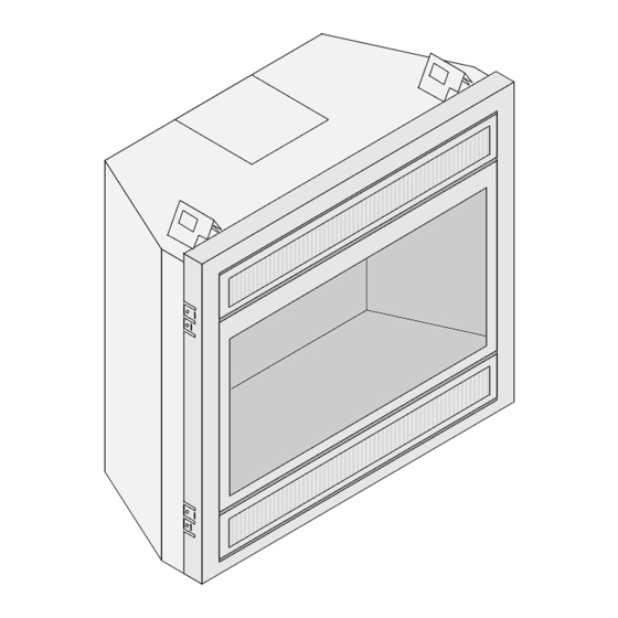
Page 14: Nailing Brackets
Installation (for qualified installers only) Nailing Brackets The fireplace has nailing brackets on both sides. Secure the fireplace to the framing. NOTE: Make sure the fireplace is square and plumb when placed in the framing. Measured corner- to-corner the fireplace should be square (approx. 54-7/8” – 1394mm). See the illustration below. Use shims to insure the fireplace is square. -
Page 15: Corner Installations - Rear Vent Configuration
Installation (for qualified installers only) Corner Installations - Rear Vent Configuration A typical 45° installation uses the framing dimensions shown in the illustration below (NOTE: all clearances still apply). Travis Firestop Minimum 1/2" (13mm) Clearance Minimum 1" (25mm) Clearance (sku 93006094) 7-1/2"... -
Page 16: Corner Installations - Top Vent Configuration
Installation (for qualified installers only) Corner Installations - Top Vent Configuration A typical 45° installation uses the framing dimensions shown in the illustration below (NOTE: all clearances still apply). Minimum 1/2" (13mm) Clearance 15-1/2" 394mm 48" Min. 1219mm Travis Industries 4140220 100-01347... -
Page 17: Gas Line Requirements
Installation (for qualified installers only) Gas Line Requirements MASSACHUSETTS INSTALLATIONS - WARNING: THIS PRODUCT MUST BE INSTALLED BY A LICENSED PLUMBER OR GAS FITTER WHEN INSTALLED WITHIN THE COMMONWEALTH OF MASSACHUSETTS. OTHER MASSACHUSETTS CODE REQUIREMENTS: Flexible connector must not be longer than 36 inches. ... -
Page 18: Gas Line Location
Installation (for qualified installers only) Gas Line Location NOTE: The shutoff valve is attached to the side of the fireplace. If using rigid pipe, the shutoff valve may be removed from the cover plate and attached to the shutoff valve inside the fireplace. Right Side Gas Line (Stock) 3"... -
Page 19: Electrical Connection (Required)
Installation (for qualified installers only) Electrical Connection (required) The electrical line to the grounded receptacle inside the fireplace must be installed by a qualified installer and must meet all local codes. Make sure the household breaker is shut off prior to working on any electrical lines. ... -
Page 20: Vent Requirements
Installation (for qualified installers only) Vent Requirements The gas appliance and vent system must be vented directly to the outside of the building, and never be attached to a chimney serving a separate solid fuel or gas-burning appliance. Each direct vent gas appliance must use its own separate vent system. -
Page 21: Approved Vent
Installation (for qualified installers only) Approved Vent Rear vent configurations use 8" (203mm) diameter Simpson Dura-Vent Model Direct-Vent Pro (or GS)*. Top vent configurations use 8" (203mm) or 6-5/8" (168mm) diameter Simpson Dura-Vent Direct-Vent Pro (or GS)*. If using 6-5/8" (168mm) diameter vent, attach the 8" (203mm) to 6-5/8" (168mm) reducer (Travis part # 98900165) to the fireplace. -
Page 22: Approved Vent Configurations
Installation (for qualified installers only) Approved Vent Configurations Restrictor Position Intake and exhaust restrictors are built into the appliance to adjust the flow rate of intake air and exhaust gases. Depending upon the vent configuration, you may be required to adjust the restrictor positions. -
Page 23: Intake Restrictor Adjustment
Installation (for qualified installers only) Intake Restrictor Adjustment The intake restrictor is located behind the accent light, on the back wall of the firebox. To adjust the restrictor, follow the steps below: Loosen the two screws holding the intake restrictor in place.. Position # 1 (open) Slide the restrictor down to the second position... -
Page 24: Diffuser Plate Adjustment
Installation (for qualified installers only) Diffuser Plate Adjustment Certain vent configurations require the diffuser plate to be adjusted (refer to the approved vent configuration charts for details). Position # 1 is stock (bent). Position # 2 is flattened. See the directions below to change the diffuser to position #2. -
Page 25: Rear Vent Configuration With Horizontal Termination (No Vertical Rise)
Installation (for qualified installers only) Rear Vent Configuration with Horizontal Termination (no vertical rise) The termination must fall within the shaded area shown in the chart. Use the indicated restrictor and diffuser positions. See the charts below to determine maximum vent Termination Optional 45°... -
Page 26: Rear Vent Configuration With Horizontal Termination (With Vertical Rise)
Installation (for qualified installers only) Rear Vent Configuration with Horizontal Termination (with vertical rise) The termination must fall within the shaded area shown in the chart. Use the indicated restrictor and diffuser positions. Up to four elbows (45° or 90°) may be used. ... -
Page 27: Rear Vent Configuration With Vertical Termination
Installation (for qualified installers only) Rear Vent Configuration with Vertical Termination The termination must fall within the shaded area shown in the chart. Use the indicated restrictor and diffuser positions. 40' (12m) max 40' (12m) max Up to four elbows (45° or 90°) may be used. -
Page 28: Top Vent Configuration With Horizontal Termination
Installation (for qualified installers only) Top Vent Configuration with Horizontal Termination The termination must fall within the shaded area shown in the chart. Use the indicated restrictor and diffuser positions. Up to four elbows (45° or 90°) may be used. ... -
Page 29: Top Vent Configuration With Vertical Termination
Installation (for qualified installers only) Top Vent Configuration with Vertical Termination The termination must fall within the shaded area shown in the chart. Use the indicated restrictor and diffuser positions. 40' (12m) max 40' (12m) max Up to four elbows (45° or 90°) may be used. -
Page 30: Termination Requirements
Installation (for qualified installers only) Termination Requirements Venting terminals shall not be recessed into a wall or siding. Minimum 9" (229mm) clearance from any door or window Roof Minimum 12" (305mm) above any grade, veranda, porch, deck or balcony Surface Minimum 1"... -
Page 31: Hearth Requirements
Installation (for qualified installers only) Hearth Requirements Do not build a hearth more than 1” (25mm) above the baseplate (this area must Floor Mounted remain clear for the access Fireplaces door). If installed near carpet or other combustible flooring, the fireplace must be raised so the base of the unit is above the carpet surface or flooring material. -
Page 32: Facing Requirements
Installation (for qualified installers only) Facing Requirements This appliance is designed to allow for drywall (or other combustible facing) to contact the sides and top of the front of the fireplace. Tile or other non-combustible facing may be placed on the front of the fireplace (see "Facing Overview"... -
Page 33: Facing Overview
Installation (for qualified installers only) Facing Overview Upgrade faces are available for this fireplace and may influence facing installation. Consult with your Travis Dealer if you are using an upgrade face. Optional non-combustible facing may be installed on the fireplace. Use the guidelines below to determine the location (also see the following pages for detailed diagrams. -
Page 34: Thin Facing Installation (Tile, Marble, Or Other Non-Combustible Under 1" (25Mm) Thick)
Installation (for qualified installers only) Thin Facing Installation (tile, marble, or other non-combustible under 1" (25mm) thick) Upgrade faces are available for this fireplace and may influence facing installation. Consult with your Travis Dealer if you are using an upgrade face. Facing is installed to this edge of the fireplace. -
Page 35: Thin Facing Installation (Tile, Marble, Under 1" (25Mm) Thick) - Side View
Installation (for qualified installers only) Thin Facing Installation (tile, marble, under 1" (25mm) thick) - Side View Drywall Raised Fireplace Tile or other facing under 1'' (25mm) (with no Hearth) thick. Face SIDE OF FIREPLACE Note how the facing extends 1'' (25mm) above the base of the fireplace. -
Page 36: Thick Facing Installation (Stone, Brick, Or Other Non-Combustible Over 1" (25Mm) Thick)
Installation (for qualified installers only) Thick Facing Installation (stone, brick, or other non-combustible over 1" (25mm) thick) If using a Fireplace Xtrordinair (FPX) arched face, see "Thick Facing with a Fireplace Xtrordinair Arched Faces" on page 37. Do not install masonry (or other material) in front of the fireplace. -
Page 37: Thick Facing With Fireplace Xtrordinair (Fpx) Arched Faces
Installation (for qualified installers only) Thick Facing with Fireplace Xtrordinair (FPX) Arched Faces The following illustration shows facing considerations for those fireplaces utilizing FPX arched faces. The facing must be non-combustible and over 1" (25mm) in depth. Masonry Line The Fireplace Xtrordinair 864 Masonry Template is recommended for masonry installation (sku 98500688). -
Page 38: Thick Facing Installation - Side View
Installation (for qualified installers only) Thick Facing Installation - Side View Drywall Floor-Mounted Fireplace (with Hearth) Masonry or other non-combustible over 1'' (25mm) thick SIDE OF FIREPLACE Face Hearth (note how it extends under the face - max. 1'' (25mm) thick). The fireplace may be raised to accommodate thicker hearth materials. -
Page 39: Mantel Requirements
Installation (for qualified installers only) Mantel Requirements Combustible Mantels Use the table below to determine the maximum mantel depth allowed. The mantel depth (measured from the face of the fireplace) must fall in the shaded portion of the table. ... -
Page 40: Installation Example - Build-Out (Dog-House) With Hor. Termination
Installation (for qualified installers only) Installation Example - Build-Out (Dog-House) with Hor. Termination The framing, facing, and other building materials depicted below are for example only. Refer to local building codes for framing, facing, and insulating requirements in your area. Side View Drywall See "Vent Termination"... -
Page 41: Installation Example - Build-In With Horizontal Termination
Installation (for qualified installers only) Installation Example - Build-In with Horizontal Termination The framing, facing, and other building materials depicted below are for example only. Refer to local building codes for framing, facing, and insulating requirements in your area. Side View Drywall See "Vent Termination"... -
Page 42: Steps For Finalizing The Installation
Finalizing the Installation (for qualified installers only) Steps for Finalizing the Installation Remove the glass (see page 44). NOTE: If using propane (LP) convert the appliance prior to installing the logs. We recommend you purge the gas line at this time (with the glass removed). This allows gas to be detected once it enters the firebox, ensuring gas does not build up. -
Page 43: Air Shutter Adjustment
Finalizing the Installation (for qualified installers only) Check the air shutter following the directions below. Air Shutter Adjustment Let the heater burn for fifteen minutes (make sure the logs and glass are in place). The flames should be yellow with no sooting. Adjust the air shutter, if necessary, to achieve the correct looking flame. Correct Not Enough Air Too Much Air... -
Page 44: Glass Frame Removal And Installation
Finalizing the Installation (for qualified installers only) Glass Frame Removal and Installation Warning: The appliance must be completely cool before removing the glass. Warning: Do not strike or slam the glass. Based upon the face being used, either: (a) swing the access door down and remove the top grill, (b) remove the face (unscrew or lift off - see the instructions included with the face for details). -
Page 45: Glass Frame Removal And Installation (Continued)
Finalizing the Installation (for qualified installers only) Glass Frame Removal and Installation (continued) The latch can come loose from glass frame anchor. This occurs when it is turned 1/4 turn when it is disengaged. Follow the directions below to re-install the latch if it becomes loose. Hold the latch at an angle and insert it into the slot on the glass frame anchor. -
Page 46: Log Set Installation
Finalizing the Installation (for qualified installers only) Log Set Installation Log Set Overview When installed, the ten (10) logs should appear as shown below. The directions on the following pages detail installation of this log set. Back Log Center Log Right Twig Left Log Center Left... -
Page 47: Back Log
Finalizing the Installation (for qualified installers only) Back Log The back log has two pockets that insert over two tabs on the back burner (see photos below). Place the log in place and push it back. The log straddles the burner and does not cover any burner holes. Right Log The right log has a channel on the bottom that fits over the grate. -
Page 48: Front Left Log
Finalizing the Installation (for qualified installers only) Front Left Log The front left log has a channel that fits over the grate. When in place the knob on the front of the log fits over the grate as well. Left Log The left log has a channel on the bottom. -
Page 49: Center Twig
Finalizing the Installation (for qualified installers only) Center Twig The center twig is shown below. It has a pin on the bottom side. When in place, the fork on the front straddles the grate and the pin rests on the rear burner (make sure it is not over any burner holes). Front Ember Chunk The front ember chunk has a groove on the bottom that fits over the grate. -
Page 50: Left Twig
Finalizing the Installation (for qualified installers only) Left Twig The left twig has a hole on the bottom that fits over the pin on the front left log. Place the twig as shown below. The front left log has a groove that will point the twig upwards and to the right. Center Left Twig The left center twig is flat on the bottom and has a fork at one end. -
Page 51: Center Log
Finalizing the Installation (for qualified installers only) Center Log The center log has a hole on the back and a fork on the front. Position the log so this fits over the pin on the back log. Make sure the fork on the front of the log fits over the grate as shown below. Right Twig The right twig has a hole on the bottom that fits over the pin on the right log. -
Page 52: Ember Installation
Finalizing the Installation (for qualified installers only) Ember Installation A bag of embers is provided to further enhance the firebox. Place the embers on the firebox floor and on the burner. Do not place embers over any of the burner holes or air channels. Rock Wool Placement The included rock wool is placed on top of the burner to enhance the glow from the burner. -
Page 53: Lp Conversion Instructions
Finalizing the Installation (for qualified installers only) LP Conversion Instructions Install the conversion kit prior to installing the gas line to ensure proper gas use. The GSR Stepper Motor Kit (SKU 94400999) is required for converting this appliance to LP. The kit contains the stepper motor (regulator), torx wrench, and pilot orifice. - Page 54 Finalizing the Installation (for qualified installers only) Follow the directions below to replace the orifice. Slide the air shutters to provide access to the orifices. Remove and discard the two gaskets on the front burner orifice. Use a 9/16" wrench to secure the Manifold manifold while removing each 9/16"...
- Page 55 Finalizing the Installation (for qualified installers only) Install the LP pilot orifice following the instructions below. (a) Use a 7/16” open-end wrench to remove the pilot hood. (b) Remove and discard the Natural Gas (NG) orifice. Place the LP orifice in the pilot assembly then replace the pilot hood, tightening the pilot hood until it is snug (do not over-tighten).
-
Page 56: Fireback Installation
Optional Equipment (for qualified installers only) Fireback Installation WARNING: Turn off gas to the appliance and make sure it has fully cooled prior to conducting service. Remove the glass frame and logs. Install the firebacks following the directions to the right (note: the hearth plate is discarded). -
Page 57: Grill Installation
Optional Equipment (for qualified installers only) Grill Installation Certain faces allow for installation of an upper and lower grill. Follow the directions below to install. Hold the grill at an angle and insert the lower Swing the grill upwards to engage the upper Upper Grill slot over the bushing on the fireplace (both slot. -
Page 58: Wiring Diagram
Optional Equipment (for qualified installers only) Wiring Diagram Accessory Power White Black Black White Accent Light (s) Optional Blower(s) Power 3 Amp Fuse 3 Amp Fuse Appliance Ground 3.15A FUSE Integrated Pilot Sensor Fireplace Flame Control Detect (IFC) Spark System Jumper Appliance Ground... - Page 59 Optional Equipment (for qualified installers only) Travis Industries 4140220 100-01347...
-
Page 60: Index
Index Index Additional Items Required ........7 LP Conversion Instructions ......53 Approved Vent Configurations ......22 Mantel Requirements ........39 Dimensions ............6 Rear Vent Configuration with Horizontal Electrical Connection ........19 Termination (no vertical rise) ......25 Facing Requirements ........32 Rear Vent Configuration with Horizontal Fireback Installation .........
Need help?
Do you have a question about the 864 TRV GSR2 and is the answer not in the manual?
Questions and answers