Table of Contents
Advertisement
Zero Clearance Direct Vent Gas Fireplace
WARNING: If the information in this manual is not followed exactly, a fire or explosion may result causing
property damage, personal injury, or loss of life.
For your safety
Do not store or use gasoline or other flammable vapors and liquids in the vicinity of this or any other appliance.
What to do if you smell gas
Do not try to light any appliance.
Do not touch any electrical switch; do not use any phone in your building.
Immediately call your gas supplier from a neighbor's phone. Follow the gas supplier's instructions.
If you cannot reach your gas supplier, call the fire department.
Installation and service must be performed by a qualified installer, service agency or the gas supplier.
Please read this manual before installing or using this appliance. Retain this manual for future reference.
TASMAN EP & HP
Natural Gas & Propane
Installation and Operating Instructions
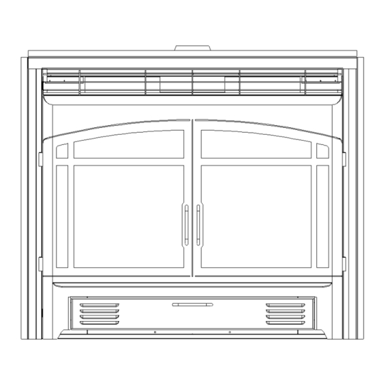
Optional Screen Door shown
See inside manual (page 59) for upgrade information
Page 1 of 80
Advertisement
Table of Contents

Related Manuals for Intertek TASMAN EP & HP


Summary of Contents for Intertek TASMAN EP & HP
- Page 1 TASMAN EP & HP Natural Gas & Propane Zero Clearance Direct Vent Gas Fireplace Installation and Operating Instructions Optional Screen Door shown WARNING: If the information in this manual is not followed exactly, a fire or explosion may result causing property damage, personal injury, or loss of life.
-
Page 2: Table Of Contents
Table of Contents INTRODUCTION........................Specifications, Appliance Dimensions & Installation Codes ........ 3 & 4 Features ........................5 Intended Use ......................5 General Safety......................6 OPERATION........................... Lighting Instructions .................... 7 & 8 Heat Output Adjustment ....................9 Fan Operation ......................9 INSTALLATION ........................Installation & Safety Notes ..................10 Unpacking .......................10 Installation .......................10 3.3.1 Minimum Clearances .................. -
Page 3: Introduction
1.0 INTRODUCTION 1.1 SPECIFICATIONS TABLE 1 ITEM NATURAL GAS (NG) PROPANE (LPG) INPUT: Hi 18,000 Btu/hr (5.27 kW) 15,000 Btu/hr (4.39 kW) INPUT: Lo 12,500 Btu/hr (3.66 kW) 12,500 Btu/hr (3.66 kW) MANIFOLD PRESSURE: Hi 3.5” w.c. (0.87 kPa) 10” w.c. (2.49 kPa) MANIFOLD PRESSURE: Lo 1.7”... - Page 4 APPLIANCE DIMENSIONS Figure 1 INSTALLATION CODES Installation must conform to local codes. In the absence of local codes, installation must conform to the National Fuel Gas Code, ANSI Z233.1, or the current CAN/CGA B149.1 Installation Codes. The unit, when installed, must be electrically grounded in accordance with local codes or, in the absence of local codes, with the National Electric Code ANSI/NFPA No.
-
Page 5: Features
1.2 FEATURES Ignition system: Standing pilot ignition system with thermopile and thermocouple flame detection and piezo igniter. Gas control: Gas control valve type: Automatic millivolt powered combination gas control valve with variable flame control for convenience and on/off switch. Optional digital remote on/off wall switch and/or optional wall thermostat (note: thermostats are not allowed in the United States). -
Page 6: General Safety
1.4 GENERAL SAFETY Maintain adequate clearances around air openings into the combustion chamber. Maintain adequate accessibility clearances for servicing and proper operation. This appliance shall not be connected to chimney flue serving a separate solid-fuel burning appliance. ... -
Page 7: Operation
2.0 OPERATION 2.1 LIGHTING INSTRUCTIONS FOR YOUR SAFETY, READ BEFORE LIGHTING WARNING: If you do not follow these instructions exactly, a fire or explosion may result causing property damage, personal injury or loss of life. This appliance has a pilot which must be lighted by hand. When lighting the pilot, follow these instructions exactly. BEFORE LIGHTING smell all around the appliance area for gas. -
Page 8: Lighting Instructions
LIGHTING INSTRUCTIONS - for Intermittent Pilot FOR YOUR SAFETY, READ BEFORE LIGHTING WARNING: If you do not follow these instructions exactly, a fire or explosion may result causing property damage, personal injury or loss of life. This appliance is equipped with an ignition device which automatically lights the pilot. Do not try to light the pilot by hand. BEFORE LIGHTING smell all around the appliance area for gas. -
Page 9: Heat Output Adjustment
2.2 HEAT OUTPUT ADJUSTMENT The valve supplied with the appliance has a HI/LO knob to control the heat output and flame height (see valve diagram in Lighting Instructions, section 2.1). 2.3 FAN OPERATION For units equipped with a fan control knob, the knob is located in the valve control compartment and may be adjusted to the following settings: OFF: Turn the control fully counter-clockwise until the switch operates. -
Page 10: Installation
3.0 INSTALLATION 3.1 INSTALLATION & SAFETY NOTES Read all instructions before starting installation and follow them carefully during installation to ensure maximum benefit and safety. Failure to follow these instructions will void your warranty and may present a fire hazard. See the warranty at the back of this manual for disclaimers regarding improper installation. -
Page 11: Minimum Clearances
3.3.1 MINIMUM CLEARANCES (continued) Figure 3 Page 11 of 80... - Page 12 3.3.1 MINIMUM CLEARANCES (continued) Mantle Height Mantle Depth (X) from Floor (Y) 40" 10" 39" 9" 38" 8" 37" 7" 36" 6" 34" 5" 33" 4" Minimum Clearances to Combustibles A – Internal Ceiling 48” (1219 mm) from floor B– Back & Sidewalls 0"...
-
Page 13: Gas Line Installation
3.3.2 GAS LINE INSTALLATION Install supply line using any piping approved for your installation meeting CAN/CGA 6.10, AA 3, ANSI Z21.24 or Z21.45. A qualified gas fitter should install the gas line in accordance with all local building codes. If codes permit, coiled copper tubing may be used for gas supply. ... - Page 14 TABLE 1 THERMOSTAT WIRE INFORMATION WIRE SIZE MAX. WIRE LENGTH 12.2 19.5 30.5 After the unit is installed and the gas line hooked up, crimp a fork connector to each wire and attach them to the TH/TP and TH screws located on the valve. 3) Check tests can be performed on the valve by using the trouble-shooting guide, Section 5.0.
-
Page 15: Direct Vent Information
3.3.4 Direct Vent Information The unit must be connected to listed 2-ply aluminium venting, 4” flex vent on the exhaust side and listed 7” flex vent on the air intake side or can be used with Security Venting or Simpson Dura-Vent 4” x 6-5/8”... - Page 16 3.3.4 Direct Vent Information (continued) Simpson Dura-Vent The minimum vent system for horizontal termination must consist of: Simpson Dura-Vent adapter Part # 0924N3 directly on top of unit 90 degree elbow 12" (305 mm) length horizontally Wall thimble part #IMC1082A Horizontal termination cap 0984 The maximum horizontal vent system consists of: Simpson Dura-Vent adapter Part # 0924N3 directly on top of unit...
- Page 17 3.3.4 Top Vent - Direct Vent Information (continued) Selkrik Direct-Temp Venting The minimum vent system for horizontal termination must consist of: Simpson Dura-Vent adapter Part # 0924N3 directly on top of unit 90 degree elbow 12" (305 mm) length horizontally Wall thimble part #IMC1082A Horizontal termination cap 4DT-HC The maximum horizontal vent system consists of:...
- Page 18 3.3.4 Direct Vent Information (continued) 2-Ply Aluminum Flex Vent The minimum vent system for horizontal termination must consist of: 10” (254 mm) vertical length (measured to center of vent pipe) with a 90 degree bend and a 10” (254 mm) horizontal length (measured from center of vent pipe) Wall thimble part# IMC1082A Horizontal termination cap part # IMC1070A or IMC1070B The maximum horizontal vent system consists of:...
- Page 19 This model is certified for a maximum horizontal run of 15’ at 40’ vertical and a maximum vertical height of 40’. Page 19 of 80...
- Page 20 TYPICAL FLEX VENT INSTALLATIONS (continued) Installation 1 With this installation a maximum of 4 - 90 degree and a maximum 30’ vertical with a maximum total horizontal offset of 15’ may be used. The installer must use a wall thimble (part # IMC1082A) wherever the venting passes through a wall, floor or ceiling.
- Page 21 3.3.4 Direct Vent Information (continued) Natural Gas EP Unit ONLY Simpson Dura-Vent The minimum vent system for horizontal termination must consist of: Simpson Dura-Vent adapter Part # 0924N3 directly on top of unit 12" (300 mm)vertical length of vent 90 degree elbow 12"...
- Page 22 3.3.4 Top Vent - Direct Vent Information (continued) Natural Gas EP Unit ONLY Selkrik Direct-Temp Venting The minimum vent system for horizontal termination must consist of: Simpson Dura-Vent adapter Part # 0924N3 directly on top of unit 90 degree elbow 12"...
- Page 23 3.3.4 Direct Vent Information (continued) Natural Gas EP Unit ONLY 2-Ply Aluminum Flex Vent The minimum vent system for horizontal termination must consist of: 10” (254 mm) vertical length (measured to center of vent pipe) with a 90 degree bend and a 10”...
- Page 24 Direct Vent Information (continued) Natural Gas EP Unit ONLY Horizontal Vents Acceptable Configurations Example 1 V Value = A (4') = 4' H Value = 3B (3 x 2') + C (3') = 11' V Value = Total length of all vertical sections in feet.
- Page 25 Direct Vent Information (continued) Natural Gas EP Unit ONLY Vertical Vents Acceptable Configurations Example 1 V Value = A (4') + C (3') = 7' H Value = 2B (2 x 2') = 4' V Value = Total length of all vertical sections in feet.
- Page 26 Direct Vent Information (continued) Natural Gas EP Unit ONLY Chart IV Page 26 of 80...
- Page 27 Typical Simpson Dura- Vent Installation: Vent terminals shall not be recessed into a wall or siding. Figure 6 Page 27 of 80...
- Page 28 USE OF COUPLERS – WITH FLEX PIPE In the event of a puncture of the vent pipe or if an extension is needed couplers may be used on both the 4” and 7” flex vent. High temperature sealant shall be applied to the ends of the coupler and then the coupler shall then be inserted into the flex vent.
- Page 29 VENT RESTRICTOR INSTALLATION Decorative Unit Restrictors Vent Configuration Restrictor Size Width (inches) 40' vertical x 15' horizontal 3.35" 20’ – 30’ 3.48” 12’ – 20’ 3.14” 6’ – 12’ 2.5” below 6’ none Heater Unit Restrictors Vent Configuration Restrictor Size Width (inches) 20’...
- Page 30 Direct Vent Information (continued) Natural Gas EP Unit ONLY Page 30 of 80...
- Page 31 Direct Vent Information (continued) Natural Gas EP Unit ONLY Page 31 of 80...
- Page 32 VENT RESTRICTOR INSTALLATION Natural Gas EP Unit ONLY Vent Configuration Restrictor Size Width (inches) 35' - 40' vertical 3.48" 25' vertical 3.35" 7' vertical 2.5" 40' vertical x 28' horizontal & 4 vertical elbows 3.48” 25' vertical x 28' horizontal & 4 vertical elbows 3.35”...
- Page 33 VENT RESTRICTOR INSTALLATION (continued) The restrictors are installed by removing the 2 screws on the ceiling of the firebox, place the desired restrictor in place and using the screws to fasten the restrictor to the firebox. If you are installing a heater unit, you must first remove the firebox baffle (4 screws) before installing the desired restrictor.
- Page 34 Horizontal Wall Vent Terminations The position of the horizontal vent termination must be positioned in such a way as to meet all local building codes. Attach the correct length of pipe. Mark the center line of the pipe facing the wall (allowing for a 1/4” rise per foot of horizontal, example 10 ft of horizontal would require a rise of 2.5”).
- Page 35 Termination above Roof Consult local codes for minimum vent cap height above the roof (X), vent must be a minimum of 2’ from any wall. Figure 10 To prevent water seepage; install the flashing with upper portion slid under the roofing material and the lower portion over the roofing material.
- Page 36 VENT TERMINAL LOCATIONS Figure 11 Vent Termination Air Supply Inlet NOTE: All clearances are measured from the center of the termination (except item F). A = clearances above grade, veranda, porch, deck, or balcony * 17-1/2" (445 mm) minimum B = clearance to window or door that may be opened *17-1/2" (445 mm) minimum C = clearance to permanently closed window *minimum 17-1/2"...
-
Page 37: Firebox Component Installation
3.3.5 CERAMIC LOG INSTALLATION – TUBE BURNER The log tray has 4 tabs (2 front, 2 back) for positioning the rear log and the main front log. Position rear log on rear log pins. Page 37 of 80... - Page 38 3.3.5 CERAMIC LOG INSTALLATION (continued) Position front log on front log pins. Position front right twig on log pin and move right side of twig until it contacts the front lip of the log tray. NOTE: The E unit is available with the above 3 log installation or with the additional twigs shown on the following page.
- Page 39 3.3.5 CERAMIC LOG INSTALLATION (continued) Position left twig on the pins located on the front and rear logs, note that the wye portion of the twig is facing the rear of the unit . Position right twig on the pin located on the rear log and move the twig until it is resting against the front twig.
- Page 40 MAIN BURNER FLAME PICTURE Decorative (E-Unit) Page 40 of 80...
- Page 41 3.3.5 CERAMIC LOG INSTALLATION – PAN BURNER The log tray has tabs (2 front, 2 back) for positioning the rear log and the main front log. Position rear log on rear log pins. Page 41 of 80...
- Page 42 3.3.5 CERAMIC LOG INSTALLATION – PAN BURNER (continued) Position right front log on front log pins. Position front left twig on log pins. Page 42 of 80...
- Page 43 3.3.5 CERAMIC LOG INSTALLATION – PAN BURNER (continued) Position far left twig on the pin located on the bottom twig and angle as shown. Position right "Y" twig on the pins located on the rear log and move the twig until it is resting on the front twig.
- Page 44 3.3.5 CERAMIC LOG INSTALLATION – PAN BURNER (continued) Position left "Y" twig on the pins located on the front and rear logs, note that the wye portion of the twig is facing the rear of the unit . Position center "Y" twig on the pins located on the right front log and left twig, note that the wye portion of the twig is facing the left side of the unit.
- Page 45 MINERAL WOOL & EMBER INSTALLATION – PAN BURNER Tasman HP For illustration purposes logs are shown without center twig. The Tasman HP is able to be operated with mineral wool & embers for additional flame effect. The mineral wool is inserted between the logs and a containment barrier, which is part of the burner. The other areas, shown along the front of the burner, may have other burner media such as embers or “lava rock”, etc.
- Page 46 MINERAL WOOL & EMBER INSTALLATION – PAN BURNER Tasman EP For illustration purposes logs are shown without center twig. The Tasman EP is able to be operated with mineral wool & embers for additional flame effect. The mineral wool is inserted between the logs and a containment barrier, which is part of the burner. The other areas, shown along the front of the burner, may have other burner media such as embers or “lava rock”, etc.
- Page 47 PAN BURNER FLAME PICTURE Decorative (E-Unit) H-Unit Page 47 of 80...
-
Page 48: Door Installation
3.3.6 Door Installation Fit the top door slots over the brackets on each side of the top of the firebox, locate the two bottom clasps and close. See Figure 12. Pull the top of the window forward and release. Make sure the door returns to it’s original position. This ensures that the door safety device is working properly. - Page 49 WARNING: Do not operate appliance with the glass front removed, cracked or broken. Replacement of the glass should be done by a licensed or qualified service person.” Only doors certified with the appliance shall be used. Do not use substitute materials. ...
-
Page 50: Initial Firing & Manifold Pressure
3.3.7 INITIAL FIRING When lit for the first few times, the appliance may emit an odour resulting from evaporation of paint and lubricants used in the manufacturing process. Open a door or window for ventilation. Anyone with a respiratory condition may need to leave the room during the initial firings. NOTE: It is normal for the appliance to expand and contract while it heats up or cools down whether this is from a cold start or a steady-state condition where the fan has come on or off. -
Page 51: Primary Air Adjustment
PRIMARY AIR ADJUSTMENT Aeration is factory set but may need adjustment for altitude or movement during shipping. To adjust the air shutter loosen the screw on the bottom of the valve tray and slide the shutter bolt right or left to suit (see Figure 14). -
Page 52: Altitude Adjustment
3.3.9 ALTITUDE ADJUSTMENT All valves have been pre-set and certified for installation at elevations from 0 – 4500 feet (1 – 1372m) above sea level. When installing this unit at higher elevations, it is necessary to decrease the input rating by replacing the existing burner orifice with a smaller size for installations over 4500 feet (1372m). -
Page 53: Field Assembled Parts
3.3.10 FIELD ASSEMBLED PARTS OPTIONAL FAN INSTALLATION The optional fan kit (part # IMC1057A) is available with a 45 mm fan. To install the optional fan you will need to have 120 VAC run to a receptacle inside the unit. Remove the bottom louver and control panel then slide the fan kit into place behind the valve and secure with 3 # 10 sheet metal screws in the holes provided on each side. - Page 54 3.3.10 FIELD ASSEMBLED PARTS (continued) LOUVERS The louvers are simple to install, the bottom & top louvers hang on brackets located at each side of the appliance. See Figure 18. Figure 18 Page 54 of 80...
- Page 55 3.3.10 FIELD ASSEMBLED PARTS (continued) Optional Bay Fronts The appliance is available with 2 optional bay fronts: IMC1027A IMC1013A Page 55 of 80...
- Page 56 3.3.10 FIELD ASSEMBLED PARTS (continued) Optional Bay Fronts Both bay fronts are installed in the same way, simply remove the existing louvers and hang the bay fronts in the slots which the louvers fit in see Figure 19. Figure 19 Page 56 of 80...
- Page 57 VENTING When Security Venting or Simpson Dura-Vent is to be used with the unit it will be necessary to install an adapter to allow the 6-5/8” venting to connect to the unit which is factory assembled for connection to 7” flex vent. The adapter (part# 0924N3) fits over the exhaust & air inlet collars on the top of the appliance and is fastened in place with sheet metal screws.
- Page 58 VENTING (continued) Figure 22 Page 58 of 80...
-
Page 59: Maintenance
4.0 MAINTENANCE 4.1 MAINTENANCE SAFETY Turn off the gas to the main burner and allow the heater to cool for up to 30 minutes before servicing. Service and repair should be done by a qualified service person. The appliance should be inspected before use and at least annually by a professional service technician. -
Page 60: Burner & Pilot Cleaning
4.4 BURNER & PILOT CLEANING Periodic cleaning is necessary for proper operation. Refer to section 4.7, remove the burner, and check that the burner orifice is clean. Visually inspect the pilot. Brush or blow away any dust, lint, or foreign debris. If the pilot orifice is plugged, disassembly may be required to remove any foreign material from the orifice or tubing. -
Page 61: Trouble Shooting
5.0 TROUBLE SHOOTING SYMPTOM CORRECTIVE ACTION POSSIBLE CAUSE Pilot will not light after A. No spark at electrode (weak or not heat source for pilot ignition) repeated triggering of the piezo ignition button 1. Improper ignition 1. Align the electrode with 1/8” (3mm) gap to pilot hood 2. - Page 62 Pilot will not stay lit after B. Defective safety circuit following the lighting 1. Loose defective 1. Check continuity, tighten wiring or instructions continued … connections connections, and repair A. Valve / Switches III. Main burner will not light 1. Valve control off 1.
-
Page 63: Replacement Parts
6.0 REPLACEMENT PARTS When requesting service or replacement parts for your unit, please provide model name and serial number. All parts listed below may be ordered from an authorized dealer. Description Part# Door IMC1009 Door Retainer IMC1043 Upper Louvers IMC1012AU Lower Louvers IMC1012AL Burner Tray... -
Page 64: Replacement Parts
6.0 REPLACEMENT PARTS (continued) Additional parts for heater units Description Part# Rear Ceramic Panel IMC1049 Right Ceramic Panel IMC1050 Left Ceramic Panel IMC1051 Burner IMC1036A Orifice P0505-37 Orifice P0505-53 Burner Tray IMC1037A Firebox Baffle IMC1042 Door Glass IMC1010A Burner Media IMC1200 Valve Tray (natural gas) IMC1040HN... -
Page 65: Warranty
7.0 INCA METAL CUTTING’S WARRANTY PROTECTION FOR ALL INCA METAL CUTTING GAS FIREPLACE PRODUCTS Inca Metal Cutting’s products are designed with superior components and materials, assembled by trained craftsmen who take great pride in their work. The burner and valve assembly are leak tested and test fired at a quality control test station. -
Page 66: Warranty
CONDITIONS AND LIMITATIONS (continued) In the first year only, this warranty extends to the repair or replacement of warranted parts, which are defective in material or workmanship provided that the product has been operated in accordance with the operation instructions and under normal conditions. After the first year, Inca Metal Cutting may, at its discretion, fully discharge all obligations with respect to this warranty by refunding to the original warranted purchaser the wholesale price of any warranted but defective part(s). -
Page 67: Label Information (E-Unit)
8.0 LABEL INFORMATION E - UNIT Page 67 of 80... -
Page 68: Inca Metal Cutting
9.0 LABEL INFORMATION (continued) Keep burner and control compartment clean. See installation and operating instructions accompanying appliance. Sections of the venting system have not been installed. WARNING – Do not operate the appliance until all sections have been assembled and installed in accordance with the manufacturer’s instructions. -
Page 69: Appendix A (H-Unit Upgrade)
APPENDIX A INSTRUCTIONS FOR TUBE BURNER UPGRADING TO HEATER UNIT The specifications of the heater unit are: ITEM NATURAL GAS (NG) PROPANE (LPG) INPUT: Hi 32,000 Btu/hr (9.37 kW) 28,000 Btu/hr (8.20 kW) INPUT: Lo 23,000 Btu/hr (6.74 kW) 22,000 Btu/hr (6.44 kW) MANIFOLD PRESSURE: Hi 3.5”... - Page 70 The steps for upgrading the decorative unit to a heater unit are as follows: 1) Remove door (see page 32). 2) Remove logs, log tray and burner. Remove orifice and replace with appropriate orifice for heater unit. Install heater burner & log tray. Page 70 of 80...
- Page 71 3) Install burner media along front edge of log tray, media may protrude to the center of the front burner holes and may be installed in any unused area along the front of the log tray. The picture below shows approximately how far the embers should protrude into the flame. 4) Install firebox baffle with 2 screws into back wall of firebox and 2 screws into ceiling of firebox.
- Page 72 5) The first step for installing the ceramic brick panels is to place the rectangular shaped panel on the log tray against the back wall of the firebox. Next slide, either, left or right panel into place, note that the panel fits behind the ledge of the firebox baffle on the top and a bent up tab on the log tray on the bottom.
- Page 73 LABEL INFORMATION H – UNIT Page 73 of 80...
- Page 74 APPENDIX B (CONVERSION KITS) This kit will convert the fireplace to Natural Gas / Propane (as applicable). In order to convert this unit to an alternate gas the valve tray assembly must be replaced as 1 piece. The IMC100 models are designed to burn either natural gas or propane. Each unit leaves the factory equipped for one specific fuel but it is simple to field convert the unit to an alternate fuel.
-
Page 75: Appendix B (Conversion Kit)
The proper steps for converting the appliance are as follows: 1) Caution the gas supply shall be shut off prior to disconnecting the electrical power, before proceeding with the conversion. 2) Remove the door, ceramic logs, log tray and burner (see page 43 in the manual). 3) Remove the valve tray (see pages 43 in the manual). - Page 76 H-Unit Propane Gas ALTITUDE (ft) ORIFICE # 2000 3000 4000 5000 6000 7000 8000 9000 10,000 E-Unit Natural Gas ALTITUDE (ft) ORIFICE # 2000 3000 4000 5000 6000 7000 8000 9000 10,000 E-Unit Propane Gas ALTITUDE (ft) ORIFICE # 2000 3000 4000 5000...
- Page 77 CONVERSION KIT MARKINGS Class IIIA Minimum inlet gas pressure 5.0” w.c. for natural gas Minimum inlet gas pressure 11.5” w.c. for propane Maximum inlet gas pressure 7.0” w.c. for natural gas Maximum inlet gas pressure 14.0” w.c. for propane Input rating 32,000/23,000 btu/hr for natural gas on Tasman HT unit Input rating 18,000/12,500 btu/hr for natural gas on Tasman ET unit Input rating 28,500/22,000 btu/hr for propane gas on Tasman HT unit Input rating 15,000/12,500 btu/hr for propane gas on Tasman ET unit...
-
Page 78: Appendix C (Intermittent Pilot & Valve Kit)
APPENDIX C (AMERICAN FLAME VALVE INFORMATION) Page 78 of 80... - Page 79 APPENDIX C (Continued) Page 79 of 80...
- Page 80 APPENDIX C (Continued) Special Features on the AF-4000 Module The AF-4000 Module can be powered two different ways. The first is a standard 110 volt AC to 6.0 volt DC adaptor. This adapter is connected to the AF-4000 Module by connecting the two 1/4” female terminals from the adapter to the two 1/4”...
Need help?
Do you have a question about the TASMAN EP & HP and is the answer not in the manual?
Questions and answers