Table of Contents
Advertisement
Quick Links
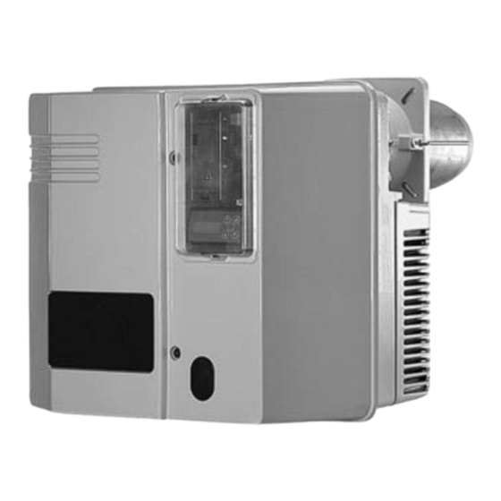
VECTRON G 05.700 MODULO
VECTRON G 05.1000 MODULO
Operating instructions
For the authorised specialist
Gas burners .........................................2-31
Ersatzteilliste
Spare parts list
Pièces de rechange
Wisselstukkenlijst
Elektro- und Hydraulikschema
Electric and hydraulic diagrams
Schémas électr. et hydraulique
Elektr. en hydraulische schema
09/2005 - Art. Nr. 13 019 526A
EN
}
Art. Nr.
13 019 525
}
Art. Nr.
13 018 839
Advertisement
Table of Contents

Related Manuals for elco VECTRON G 05.700 MODULO


Summary of Contents for elco VECTRON G 05.700 MODULO
- Page 1 VECTRON G 05.700 MODULO VECTRON G 05.1000 MODULO Operating instructions For the authorised specialist Gas burners .........2-31 Ersatzteilliste Spare parts list Art. Nr. Pièces de rechange 13 019 525 Wisselstukkenlijst Elektro- und Hydraulikschema Art. Nr. Electric and hydraulic diagrams 13 018 839 Schémas électr.
-
Page 2: Table Of Contents
Description of burner, Scope of that the products delivery, Optional accessories.....4 Technical data, Power graphs ....5 VECTRON G 05.700 MODULO Gas valve selection ......6 VECTRON G 05.1000 MODULO Dimensional drawings and measurements ........7 conform to the following standards Gas valve assembly ......8... -
Page 3: Overview
Overview Important notes Basic regulations Important instructions The guarantee does not cover The following standards should be The G 05.700/1000 MODULO burners damage resulting from: observed in order to ensure safe, · Inappropriate use are designed to burn natural gas or environmentally sound and propane gas in category II 2 ELL 3P. -
Page 4: Description Of Burner, Scope Of
Overview Description of burner Burner description Scope of delivery Optional accessories: The G 05.700/1000 MODULO burners The burner is supplied in three Separate air intake box – are low emission, modulating gas packaging units: Air intake silencer – · Burner housing with operating burners with a monoblock type Gas stop valve –... -
Page 5: Technical Data Power Graphs
Overview Technical Data Power graphs Type description G 05.700 MODULO G 05.1000 MODULO Burner power 140-700 170-1040 Operating mode two-stage sliding/modulating Fuel Natural gas (LL, E) Hi = 8.83-10.35 kWh/m or propane gas (F) Hi = 25.89 kWh/m Gas valve DMVSE DMVSE DMVSE... -
Page 6: Gas Valve Selection
Overview Gas valve selection N.B.: The gas pressure loss specified in the The calculated gas flow pressure is to table is to be added on to the combus- be complied with at the gas valve inlet. tion chamber pressure in mbar. To calculate the gas flow pressure required at the transfer station, the resistance of the burner supply conduit... -
Page 7: Dimensional Drawings And Measurements
Overview Dimensional drawings and measurements G 05.700/1000 MODULO With DMV SE gas valve Space requirements There should be a space of no less than 0.60 m on each side of the burner for maintenance purposes. Gas valve assembly The valve assembly can be fitted on the left or the right. -
Page 8: Gas Valve Assembly
Overview Gas valve assembly The gas valve assembly consists of: a gas throttle controlled by a – servomotor a DMV-SE gas valve – a gas filter (pocket filter or external filter) – a thermally triggered safety cut-off – valve and a gas ball valve are to be provided by the manufacturer. -
Page 9: Hydraulics Diagrams
Overview Hydraulics diagram 09/2005 - Art. Nr. 13 019 526A... -
Page 10: Control Panel
Overview Control panel Function Standardised position for fitting three-point regulator Display and operating unit A4.1 Mounting location with clips for removing the display and operating unit Flame signal measuring bridge (concealed) Fuse S1/H10 Main switch 0 Off 1 On (operating light in switch lights up). Operating mode selector switch Auto/Manual N + Manual increase of... -
Page 11: Function Description
Overview Combustion control unit MPA22 Function description In addition to the function of a gas combustion control unit, the MPA 22 combustion control unit also realises power modulation of the burner via the actuation of air flaps and gas throttle in an electronic connection. -
Page 12: Display And Operating Unit
Overview Combustion control unit MPA 22 Display and operating unit Display Button · Access to Info mode (t < 5 s). · Access to voice mode (t > 5 s). · Return to next highest program level. · Activating a function. ·... -
Page 13: Programme Structure
Overview Combustion control unit MPA 22 Program structure Voice mode Adjustment mode Enter access code Parameter t>5 s Cold adjustment Hot adjustment adjustment Temperature controller on – eBus address Burner start-up Set key data – Reventilation time P9/P1/P0 – Waiting time ·... -
Page 14: Assembly
Assembly Burner head Burner housing Fitting the burner head Boiler door preparation · Screw M10 stay bolts into the · Prepare the burner plate/boiler doors burner plate/boiler door and add the as per the drawing. · Stipulate interior diameter Ø 195 mm. insulation. -
Page 15: Gas Valve Assembly
Assembly Gas valve assembly Assembly Gas valve assembly · Press the gas throttle module 5 against the burner head and tighten the 4 nuts. Then secure the gas connection pipe 3 to the gas throttle module. Check that O-Ring 6 and flat gasket 4 are in the correct position. -
Page 16: Checking/Setting Mixer Unit For Natural Gas/Propane Gas
Assembly Checking/Setting Mixer unit for natural gas/propane gas Checking the mixing unit · Check and adjust the setting of the ignition electrodes and the turbulator. Recommended setting for natural gas On the gas diffusers labelled A, 5 outwards-facing slots and 1 inwards-facing slot should be left covered by sleeve E. -
Page 17: Gas Supply Electrical Supply
Assembly Gas supply Electrical supply The installer must hold a licence issued General regulations for the gas supply · Connection of the gas valve by the gas authority, must have checked the system for leaks and must assembly to the gas mains must be have vented it. -
Page 18: Start-Up
Start-up Default settings Natural gas settings table G 05.700 MODULO Burner power Dimension Air flap opening Gas throttle opening Pressure adjustment Low load Rated load Ignition Low load Rated load Ignition Low load Rated load setting load P1 (°) P9 (°) load P1 (°) P9 (°) -
Page 19: Burner Head, Gas And Air Pressure Switch Settings, Gas Pressure Regulator
Start-up Burner head position setting, Gas pressure switch and air pressure switch Burner head position Dimension Y is set by turning screw V. Set the burner head setting in accordance with the table. The burner head setting can influence the starting performance and burner performance. -
Page 20: Checks Before Start-Up
Start-up Checks before start-up Control unit auto-test · Check the flame pipe insertion depth · Check the direction of rotation of the Pre-start-up check in accordance with the boiler fan motor (see arrow on burner · Disconnect the burner by unplugging manufacturer’s instructions. -
Page 21: Access
Start-up Access to adjustment mode Parameters menu: Programming additional functions It is only possible to access adjustment During the setup process, a timeout of N.B.: mode when the burner is idle (display: 30 minutes is active, which is reset by Only a specialist with sufficient “Control unit unprogrammed”... -
Page 22: Adjustment Mode
Start-up Adjustment mode Parameters menu: programming of additional functions Rest pos. Air flap This parameter allows you to adjust the rest position of the air flap. – This parameter (in degrees) may be required after reventilation. 00.0° Default setting 00.0° Next Back With this function, accumulated errors are deleted from the error log... -
Page 23: Cold Adjustment Menu
Start-up Adjustment mode Cold adjustment menu: Burner pre-adjustment Cold adjustment (with ball valve closed) In the “Cold adjustment” menu item, the P9/P1/P0 key data are pre-adjusted in accordance with the setting table (page 18) for the desired burner power. The control unit then calculates the intermediate points P2 to P8 and switches to the “Hot adjustment”... -
Page 24: Hot Adjustment Menu
Start-up Adjustment mode Hot adjustment menu: Adjusting the burner Ž Hot adjustment (with first start for function check, still with closed ball valve) Hot adjustment of the burner In the “Hot adjustment” menu items, the fine adjustments for the air and gas flap are made for the ten adjustment points P0 to P9 using the exhaust gas analysis. - Page 25 Start-up Adjustment mode Hot adjustment menu: adjusting the burner Burner remains in ignition load, adjustment point P0. Ignition load · Check gas pressure pBr (for factory setting, see default setting on page 18). Air: .. ` . Gas: ..´ . In the event of a later change, all adjustment settings must be corrected.
-
Page 26: Operating Mode
Start-up Operating mode Burner ready for operation Standby Boiler thermostat requests heat. Burner start flowchart: Burner check Air: Gas: The burner starts with the following function sequence: Air flap opens for ventilation. Air: ......–... -
Page 27: Info Mode
Start-up Info mode Voice mode Comment: info mode can be activated with the button during burner operation and burner idle time. To exit info mode, press the button again. Establishing connection · Press key t < 5s. 100% · Select desired menu with Error Counter Parameter... -
Page 28: Maintenance
Maintenance Burner and boiler servicing can only carried out by a trained specialist. The system operator is advised to take out a service contract to guarantee regular servicing. N.B.: Before maintenance and cleaning work, completely separate the burner from the mains, including the power supply AC motor, and close the gas ball valve. -
Page 29: Maintenance
Maintenance Replacing the filter on the gas valve Remove the blast tube. Valves The filter must be checked once a year To carry out this procedure, the No special maintenance is required for and replaced if dirty. combustion chamber door must be the valves. -
Page 30: Burner-Specific Adjustment Settings Of The Mpa 22
Burner-specific adjustment settings of the MPA 22 System: .......... Boiler manufacturer: ....... Burner No.: ........Boiler type: ..........Measurement/Date: Parameters Range eBus address Reventilation time 0-240 Waiting time [min] 0-100 Pulses per L/m³ 1-255 Rest pos. Air flap [°] Delete error list blank/ Check seals Valve check time 1... -
Page 31: Troubleshooting
Service Troubleshooting · Is there any current? Fault diagnosis and repair · Is there any gas pressure? Before carrying out fault diagnosis, · Is the gas stop valve open ? check that the basic requirements for correct operation are being fulfilled: ·... - Page 32 Adresse Service-Hotline ELCO Austria GmbH Aredstr.16-18 0810-400010 2544 Leobersdorf ELCO Belgium n.v./s.a. Pontbeeklaan-53 02-4631902 1731 Zellik ELCOTHERM AG Sarganserstrasse 100 0848 808 808 7324 Vilters ELCO GmbH Dreieichstr.10 0180-3526180 64546 Mörfelden-Walldorf ELCO France 18 rue des Buchillons 0450877624 74106 Annemasse ELCO-Rendamax B.V.
Need help?
Do you have a question about the VECTRON G 05.700 MODULO and is the answer not in the manual?
Questions and answers