Table of Contents
Advertisement
Available languages
Available languages
Quick Links
VECTRON G 06.1200 DUO PLUS
VECTRON G 06.1600 DUO PLUS
VECTRON G 06.2100 DUO PLUS
Betriebsanleitung
Für die autorisierte Fachkraft
Gasgebläsebrenner .............................2-21
Operating instructions
For the authorized specialist
Gas burners .......................................22-41
Ersatzteilliste
Spare parts list
Pièces de rechange
Wisselstukkenlijst .............................43-54
Elektro- und Hydraulikschema
Electric and hydraulic diagrams
Schémas électr. et hydraulique
Elektr. en hydraulische schema
07/2006 - Art. Nr. 13 018 114C
}
Art. Nr.
13 018 315
DE
EN
Advertisement
Chapters
Table of Contents

Related Manuals for elco VECTRON G 06.1200 DUO PLUS


Summary of Contents for elco VECTRON G 06.1200 DUO PLUS
- Page 1 VECTRON G 06.1200 DUO PLUS VECTRON G 06.1600 DUO PLUS VECTRON G 06.2100 DUO PLUS Betriebsanleitung Für die autorisierte Fachkraft Gasgebläsebrenner ......2-21 Operating instructions For the authorized specialist Gas burners ........22-41 Ersatzteilliste Spare parts list Pièces de rechange Wisselstukkenlijst ......43-54 Elektro- und Hydraulikschema Art.
-
Page 2: Table Of Contents
Feuerungsautomat ....11 Montage Brennermontage ....12 VECTRON G 06.1200 DUO PLUS Gasarmaturmontage, Dichtheitskontrollgerät . . . 13 VECTRON G 06.1600 DUO PLUS Prüfung / Einstellung . -
Page 3: Technische Daten Arbeitsfelder
Übersicht Technische Daten Arbeitsfelder G 06.1200 DUO PLUS G 06.1600 DUO PLUS G 06.2100 DUO PLUS Brennerleistung min.-max. 230 - 1200 230 - 1600 260 - 2100 Regelbereich 1 : 3 * Gasfließdruck mbar 20 - 50- 100 Gasarmaturengruppe MBVEF 412 / MBVEF 420 / VGD20 Rp2 / VGD40 DN65 Brennstoff Erdgas (LL, E) H = 8,83 - 10,35 kWh/m... -
Page 4: Gasarmaturenauswahl
Overview Selection of gas valve assembly · The gas-flow pressure determined is and its fittings (ball valve, TAS, Selection of gas-valve assembly · The gas-pressure loss indicated in additional filter or meter). to be maintained at the inlet of the ·... -
Page 5: Brennerbeschreibung
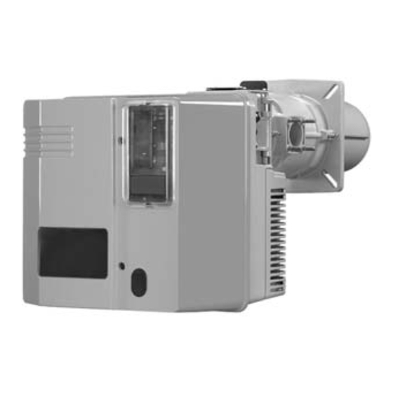
Übersicht Brennerbeschreibung Feuerungsautomat Ionisationsbrücke Luftdruckwächter Motorschutzrelais Motorschutz Relais Brennermotor Zündtransformator (verdeckt) Schaltfeld Stellantrieb Luftklappe Flammrohr Brennerhaube Luftkasten 07/2006 - Art. Nr. 13 018 114C... -
Page 6: Abmessungen
Übersicht Maßbild und Abmessungen G 06.1200/1600/2100 DUO PLUS mit Gasarmatur MBVEF 412 und MBVEF 420 MBVEF 412 MBVEF 420 — — — Abstände Für Servicearbeiten ist ein freier Abstand von min. 0,6m auf jeder Seite des Brenners sicherzustellen. Gasarmaturgruppe Montage sowohl links als auch rechts möglich. - Page 7 Übersicht Maßbild und Abmessungen G 06.1200/1600/2100 DUO PLUS mit Gasarmatur VGD20 - Rp2 und VGD40 - DN65 VGD20 Rp2 VGD40 DN65 DN65 Abstände Für Servicearbeiten ist ein freier Abstand von min. 0,6m auf jeder Seite des Brenners sicherzustellen. Gasarmaturgruppe Montage sowohl links als auch rechts möglich.
-
Page 8: Kompaktarmatur
Funktion Kompaktarmatur MBVEF Elektroanschluß des Gasdruckwächters (DIN 43650) Elektroanschluß der Magnetventile (DIN 43650) Gasdruckwächter Eingangsflansch Druckmeßnippel R1/8, vor Filter (beidseitig) Filter (unter Deckel) Typenschild Anschluß Luftdruckleitung pL, R 1/8 Einstellschraube für Verhältnis V Druckmeßnippel pe, vor Ventil 1, beidseitig Gasdruckmeßnippel M4 nach Ventil 2 Einstellschraube Nullstellung N Die Gaskompaktarmatur MBVEF ist die... - Page 9 Funktion Gasarmatur VGD mit SKP 75 Regler Elektroanschluß des Gasdruckwächters (DIN 43650) Elektroanschluß der Magnetventile (DIN 43650) Gasdruckwächter Eingangsflansch Druckmeßnippel R1/8, vor Filter Filter (unter Deckel) Typenschild Anschluß Luftdruckleitung pL, R 1/8 Einstellschraube für Verhältnis V Einstellschraube Nullstellung N Anschluß Feuerraumdruckleitung pF, R1/8 Anschluß...
-
Page 10: Schaltfeld Tc
Funktion Schaltfeld TC Funktion Genormte Einbaustellen 48x48 oder 48x96 mm für den Einbau eines Leistungsreglers (Option) A4.1 Einbaustelle mit Klips für Anzeigeeinheit B10 Messbrücke [µA DC] für Zellenstrom, Anordnung neben dem Motorschütz F10 Sicherung Hauptschalter Ein, grüne Kontroll-Lampe H10 leuchtet Wahl der Leistungsregelung Handbetrieb Auto Vorort-Automatikbetrieb... -
Page 11: Feuerungsautomat
Funktion Kenndaten des Feuerungsautomaten SG 513 Programmablauf des Feuerungsautomaten Der Gasfeuerungsautomat SG 513 steuert und Drücken Sie auf … führt zu … überwacht den Gebläsebrenner. Durch den den Knopf R mikroprozessor-gesteuerten Programmablauf ergeben sich äußerst stabile Zeiten, unabhängig von während ... Schwankungen der Netzspannung oder der …... -
Page 12: Brennermontage
Montage Brennermontage Montage Brennkopf Langlöcher auf das erforderliche · Brennerplatte/Kesseltüre gemäß Maß ausschneiden. · Brennkopf mit 4 Sechskantmuttern nebenstehender Zeichnung vorbereiten. M12 befestigen. · Innendurchmesser a Ø 250 mm · Der Raum zwischen Flammrohr und Türisolierung ist mit feuerfestem festlegen. ·... -
Page 13: Gasarmaturmontage, Dichtheitskontrollgerät
Montage Gasarmaturmontage Dichtheitskontrollgerät VPS 504 S01 · Bei SKP 75 das mitgelieferte Montage Gasarmatur SKP75/MBVEF · Die richtige Einbaulage des Sicherheitsmagnetventil (Bausatz) mit Spule nach oben montieren, den O-Ringes B im Gasanschlußflansch mitgelieferten Gasfilter (Bausatz) C überprüfen. · Die Gasarmatur mit Muttern M10 so waagerecht mit obenliegendem Deckel (2 Messanschlüsse) befestigen, daß... -
Page 14: Prüfung / Einstellung
Montage Kontrolle Mischeinrichtung Sekundärluft Einstellung Mischeinrichtung für Erdgas / Flüssiggas Kontrolle Mischeinrichtung · Sicherungsschraube D lösen (S. Seite 12). · Mobile Achse E entfernen. · Brennergehäuse öffnen. · Zünd- und Ionisationskabel lösen. · Die vier Schrauben der Einstellplatte (RTC) um 2 Umdrehungen lösen. ·... -
Page 15: Gasversorgung, Elektrische Versorgung
Montage Gasversorgung Elektrische Versorgung Prüfung vor Inbetriebnahme Bei der Inbetriebnahme des Brenners Allgemeine Vorschriften für die wird gleichzeitig die Anlage unter der Gasversorgung · Der Anschluss der Gasarmatur an Verantwortung des Installateurs oder seines Stellvertreters abgenommen. Er das Gasnetz darf nur von einer allein kann gewährleisten, dass die anerkannten Fachkraft durchgeführt Anlage den geltenden Normen und... -
Page 16: Brennereinstelldaten
Inbetriebnahme Brennereinstelldaten Luftregulierung Luftklappenstellung (°) Maß Brenner- leistung Zündlast Vollast Nocke III Nocke I G 06.1200 DUO PLUS 1100 1200 1100 G 06.1600 DUO PLUS 1300 1600 1150 1400 1700 G 06.2100 DUO PLUS 1900 2100 Obige Einstelldaten sind Grundeinstellungen. Die Werkseinstelldaten sind fett umrandet. Mir diesen Einstellungen kann im Normalfall der Brenner in Betrieb genommen werden. - Page 17 Inbetriebnahme Luftregulierung Luftregulierung über Luftklappe Diese wird über den Stellmotor Y10 angetrieben. Die Position der Luftklappe wird durch Einstellung der Nocken I - IV festgelegt. Stellindex der Nocken Vier einstellbare Nocken Schlüssel zur Nockeneinstellung Scheibe mit Skala ; gibt Stellung der Luftklappe an Knopf zur Entkupplung der Luftklappe von Stellantrieb Anschlußleiste...
-
Page 18: Einregulierung Des Brenners
Inbetriebnahme Einregulierung des Brenners Einstellung Gasdruckwächter, Luftdruckwächter Funktionskontrolle · Haben sich die Meßwerte durch Einregulierung des Brenners – bei MB VEF Ventil auf Schraube V · Gaskugelhahn öffnen. wirken. Höheres CO in Richtung Verstellen der Schraube D beim · Gas- und Luftdruckwächter auf grösserer Skalenwert. -
Page 19: Wartung
Service Wartung Servicearbeiten an Kessel und Brenner führt ausschließlich die geschulte Fachkraft durch. Um eine turnusgemäße Durchführung der Servicearbeiten zu gewährleisten sollte dem Betreiber der Anlage der Abschluß eines Wartungsvertrages empfohlen werden. · Vor Wartungs- und Reinigungsarbeiten, Strom abschalten. · Handabsperrventil schließen ·... - Page 20 Service Wartung Flammrohr demontieren Ventile Filteraustausch Gas Dieser Arbeitsvorgang macht entweder Die Ventile erfordern keine besondere Der Filtereinsatz muß einmal jährlich das Öffnen der Feuerraumtür oder die Wartung. kontrolliert und wenn verschmutzt Demontage des Brenners erforderlich. Es ist keine Reparatur an einem Ventil ausgetauscht werden.
-
Page 21: Störungsbeseitigung
Service Störungsbeseitigung Ursachen und Beseitigung von Wenn die Störung weiter besteht: Nur Originalersatzteile · Die vom Feuerungsautomat Störungen verwenden. Bei Störungen müssen die abgegebenen Blink-Codes beachten grundsätzlichen Voraussetzungen zum und ihre Bedeutung aus Hinweis: nachstehender Tabelle entnehmen. ordnungsgemäßen Betrieb kontrolliert Nach jedem Eingriff: Mit dem als Zubehör erhältlichen ·... -
Page 22: Contents
TC control panel....30 VECTRON G 06.1200 DUO PLUS Control unit ....31 Installation Burner assembly . -
Page 23: Technical Data Power Graphs
Overview Technical data Power graphs G 06.1200 DUO PLUS G 06.1600 DUO PLUS G 06.2100 DUO PLUS Burner power min.-max. 230 - 1200 230 - 1600 260 - 2100 Control ratio 1 : 3 * Gas flow pressure mbar 20 - 50- 100 Gas valve assembly MBVEF 412 / MBVEF 420 / VGD20 Rp2 / VGD40 DN65 Fuel... -
Page 24: Selection Of Gas Valve Assembly
Overview Selection of gas valve assembly · The gas-flow pressure determined is and its fittings (ball valve, TAS, Selection of gas-valve assembly · The gas-pressure loss indicated in additional filter or meter). to be maintained at the inlet of the ·... -
Page 25: Burner Description
Overview Burner description Control unit Ionisation bridge Air pressure switch Contactor thermal relay Ventilation motor contactor Relays Burner motor Ignition transformer (hidden) Control panel Servomotor of flap Blast tube Burner cover Air box 07/2006 - Art. Nr. 13 018 114C... -
Page 26: Dimensions
Overview Space requirements and dimensions G 06.1200/1600/2100 DUO PLUS with gas valve assembly MBVEF 412 and MBVEF 420 MBVEF 412 MBVEF 420 — — — Distances Maintain a clear distance of at least 0.6m to each side of the burner to allow for maintenance operations. - Page 27 Overview Space requirements and dimensions G 06.1200/1600/2100 DUO PLUS with gas valve assembly VGD20 - Rp2 and VGD40 - DN65 VGD20 Rp2 VGD40 DN65 DN65 Distances Maintain a clear distance of at least 0.6m to each side of the burner to allow for maintenance operations.
-
Page 28: Compact Valve Assembly
Function Compact valve assembly MBVEF Electrical connection for gas pressure switch (DIN 43650) Electrical connection for magnetic valves (DIN 43650) Gas pressure switch Input flange Pressure measuring nipple R1/8, ahead of filter (both sides) Filter (under cover) Type plate Connection for air pressure pipe pL R1/8 Setting screw for V ratio Pressure measuring nipple pe,... - Page 29 Function VGD gas valve assembly with SKP controller Electrical connection for gas pressure switch (DIN 43650) Electrical connection for magnetic valves (DIN 43650) Gas pressure switch Input flange Pressure measuring nipple R1/8, ahead of filter (both sides) Filter (under cover) Type plate Connection for air pressure pipe pL R1/8...
-
Page 30: Tc Control Panel
Function TC Control panel Functions Standard 48x48 or 48x96 mm positions for the installation of a power controller (optional) A4.1 Position with clips for the display B10 Mesuring bridge [µA DC] for cell current, placed next to the motor contactor F10 Fuse Main switch ON, green light... -
Page 31: Control Unit
Function Control unit SG 513 Operating diagram The SG 513 gas control unit controls and monitors the forced-draught burner. The microprocessor- Press button … leads to … controlled program sequence ensures the “R” maximum consistency of the time periods involved, regardless of fluctuations in the power-supply for ... -
Page 32: Burner Assembly
Installation Burner assembly · Screw the M12 stay bolts into the Fitting the burner head · Prepare the burner fixing plate/boiler burner fixing plate/boiler door and apply the insulation material. With a door as per the drawing. · Establish the internal diameter a at slot diameter <... -
Page 33: Assembly Of The Gas Valve Assembly, Leak Controller
Installation Assembly of the gas valve assembly Leak controller VPS 504 S01 · For SKP75, assemble the back-up Installation of valve assembly SKP70/MBVEF solenoid valve provided (kit) with the · Check the correct position of the coil towards the top, the gas filter (kit) horizontally, and with the lid up O-ring B in the gas connecting (2 connectors). -
Page 34: Checking / Setting
Installation Check combustion head Secondary air Combustion head setting for natural gas/propane Check combustion head · Unscrew the safety screw D (see page 32). · Remove the mobile spindle E. · Open the burner body. · Unplug the ignition cables and the ionisation cable. -
Page 35: Gas Supply, Electrical Supply
Installation Gas supply Electrical supply Pre-startup check The act of startup places the system General regulations applying to gas under the joint responsibility of the user supply · The gas-valve assembly MUST be and the fitter engaged to carry out installation, or the latter's connected to the gas supply network corresponding legal representative. -
Page 36: Burner Adjustment Data
Startup Burner adjustment data Airflow control Position of the flap (°) Dimension Burner power Type Full load Ignition load Cam III Cam I G 06.1200 DUO-PLUS 1100 1200 1100 G 06.1600 DUO-PLUS 1300 1600 1150 1400 1700 G 06.2100 DUO-PLUS 1900 2100 The above adjustment data correspond to the default settings. -
Page 37: Airflow Control
Startup Airflow control Airflow regulation using an air flap. This is actuated by the servomotor Y10. The position of the air flap is determined by adjusting cams I - IV. Index of cam settings Four adjustable cams Key to cam settings Graduated disk;... -
Page 38: Burner Adjustment
Startup Burner adjustment Gas pressure switch / air pressure switch adjustment Checking for correct functioning · To reach the desired yield, respect Adjusting the burner If combustion values are correct, · Open the gas ball valve. continue as follows for the part-load and combustion values as ·... - Page 39 Servicing Maintenance All boiler and burner servicing work should be carried out by an appropriately trained heating service specialist. It is recommended to enter into a maintenance contract in order to ensure that servicing is carried out at the intervals prescribed. ·...
- Page 40 Servicing Maintenance Remove the flame tube. Valves Replace the gas filter To carry out this procedure, the furnace The gas valves require no special The filter component must be controlled door must be opened or the burner servicing. annually and replaced if clogged. ·...
-
Page 41: Troubleshooting
Servicing Troubleshooting Fault diagnosis and repair If the malfunction persists: Use ORIGINAL spares only. · Note any blink-codes emitted by the Before carrying out fault diagnosis, check that the basic requirements for control unit, and check their Note: correct operation are being fulfilled: meaning with the following table. - Page 42 07/2006 - Art. Nr. 13 018 114C...
- Page 43 Ersatzteilliste Spare parts list Pièces de rechange Wisselstukkenlijst VECTRON G 06.1200 DUO-PLUS VECTRON G 06.1600 DUO-PLUS VECTRON G 06.2100 DUO-PLUS 07/2006 - Art. Nr. 13 018 114C...
- Page 44 07/2006 - Art. Nr. 13 018 114C...
- Page 45 07/2006 - Art. Nr. 13 018 114C...
- Page 46 07/2006 - Art. Nr. 13 018 114C...
- Page 47 07/2006 - Art. Nr. 13 018 114C...
- Page 48 07/2006 - Art. Nr. 13 018 114C...
- Page 49 07/2006 - Art. Nr. 13 018 114C...
- Page 50 07/2006 - Art. Nr. 13 018 114C...
- Page 51 07/2006 - Art. Nr. 13 018 114C...
- Page 52 07/2006 - Art. Nr. 13 018 114C...
- Page 53 07/2006 - Art. Nr. 13 018 114C...
- Page 54 Maintenance parts are parts which should be replaced on a preventive basis during maintenance when reassembling disassembled parts (sealing components for example).. For wear parts and maintenance parts, ELCO ’s performance warranty for them over time under commercial conditions does not apply.
- Page 55 07/2006 - Art. Nr. 13 018 114C...
- Page 56 Adresse Service-Hotline ELCO Austria GmbH 0810-400010 Aredstr.16-18 2544 Leobersdorf ELCO Belgium nv/sa Z.1 Researchpark 60 02-4631902 1731 Zellik ELCOTHERM AG Sarganserstrasse 100 0848 808 808 7324 Vilters ELCO GmbH 0180-3526180 Dreieichstr.10 64546 Mörfelden-Walldorf ELCO France 18 rue des Buchillons 0450877624 74106 Annemasse ELCO-Rendamax B.V.
Need help?
Do you have a question about the VECTRON G 06.1200 DUO PLUS and is the answer not in the manual?
Questions and answers