Table of Contents
Advertisement
VG2.120 M/TC
VG2.160 M/TC
VG2.210 M/TC
Original operating instructions
For authorised specialist engineers
Gas burners ........................................... 2-31
de, fr..................................... 4200 1038 2500
it, nl ...................................... 4200 1038 2600
............................................. 4200 1038 2400
09/2014 - Art. Nr. 4200 1038 2700A
en
Advertisement
Table of Contents

Related Manuals for elco VG2.120 M/TC


Summary of Contents for elco VG2.120 M/TC
- Page 1 VG2.120 M/TC VG2.160 M/TC VG2.210 M/TC Original operating instructions For authorised specialist engineers Gas burners ........... 2-31 de, fr........4200 1038 2500 it, nl ........4200 1038 2600 ..........4200 1038 2400 09/2014 - Art. Nr. 4200 1038 2700A...
-
Page 2: Table Of Contents
Terminal allocation chart ............6-7 "Site A" declare under our sole Control and safety unit BT 3xx gas operation ......8 responsibility that the products BT 3xx menu overview ...............9 VG2.120 M/TC MBC-SE gas train..............10 VG2.160 M/TC Burner assembly ..............11 Assembly VG2.210 M/TC... -
Page 3: Burner Description
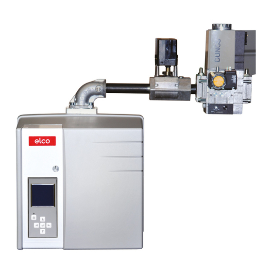
Overview Burner description Control and safety unit Display Air pressure switch Blower motor Igniter Y10 Air flap servomotor Adjusting knob for dimension Y Propane diffuser Housing Plate hanging device (Maintenance) Burner tube 7-pin connector 10.1 4 pin connector Gas connecting flange Cover Release knob Hood securing screw... -
Page 4: Operation Safety Function
Operation Operation Safety function The ionisation current must be at least Description of functions When first powering up, after a power 8 µA. cut or a lockout, after the gas supply has been cut or after a shutdown for 24 Safety functions hours, a gas valve sealing test is - If no flame is produced when the... -
Page 5: Control And Safety Unit Bt 3Xx
Operation Control and safety unit BT 3xx The control and safety unit BT 3xx Manual locking and unlocking controls and monitors the forced draught Using the reset button , the control gas burner. The microprocessor- and safety unit can be locked manually controlled program sequence ensures (interlocked) or unlocked, provided the the maximum consistency of the cycle... -
Page 6: Terminal Allocation Chart
Operation Terminal allocation chart additional Flame check Ionisation L1 power supply Grounding of Fault Burner motor Flame the burner display UV detector monitor Connector 1 2 3 1 2 3 1 2 3 4 Terminal Terminal 1 2 3 1 2 3 1 2 3 Connector Min. -
Page 7: Terminal Allocation Chart
Operation Terminal allocation chart Terminal 1 2 3 4 5 6 1 2 3 4 5 6 1 2 3 4 5 6 1 2 3 4 5 6 1 2 3 4 5 6 Connector Fuel oil PC interface Display servomotor* servomotor*... -
Page 8: Control And Safety Unit Bt 3Xx Gas Operation
Operation Control and safety unit BT 3xx gas operation Boiler safety circuit Gas safety circuit Burner on Minimum gas pressure switch Air pressure switch Flame signal Air flap Gas flap Transformer Gas valve 1 Gas valve 2 Air motor Fault Safety time Legend to the sequence diagram Operating phase... -
Page 9: Bt 3Xx Menu Overview
Operation BT 3xx menu overview In addition to the function of control and over the burner's entire output Operating values are shown in real time safety unit, the control and safety unit BT modulation range. on the display. 3xx also modulates the burner output by A separate burner ignition load can be Pressing the keys gives access to 9 controlling the air flap, gas flap, fuel oil... -
Page 10: Mbc-Se Gas Train
Operation MBC-SE gas train The gas train consists of: - a gas connection flange 1 with O-ring - a gas throttle 2, controlled by a servomotor - a gas connection pipe 3 - an MBC-SE gas valve train with gas filter 4 (mini filter) MBC SE gas valve Electrical connection of solenoid... -
Page 11: Burner Assembly
Installation Burner installation Burner installation Installation: Burner flange 3 is equipped with • Secure connecting flange 3 to the elongated slots and can be used with a boiler using screws 4 hole Ø of 150 - 184 mm. These • Fit pipe bracket 2 to the burner pipe dimensions comply with EN 226. -
Page 12: Gas Train
Installation Gas train Gas train installation • Check the correct position of the O- ring J1 in the connecting flange. • Secure the gas train on the burner so that the gas train coils are in the upper vertical position. •... -
Page 13: Checking The Combustion Components
Installation Checking the combustion components Checking the combustion components • Remove the three screws W from the cover. • Remove the cover. • Loosen lock nut E on the gas pipe bracket • Loosen the retaining bolt. • Remove combustion components. Setting to propane gas operation VG2.120 burner •... -
Page 14: Electrical Connection
Installation Electrical connection Checks before commissioning Ionisation current measurement specified by the draft combustion General regulations applying to the ordinance. gas connection • The gas train must only be connected It is the responsibility of the fitter or his to the gas mains by a recognised representative to obtain approval for the specialist. -
Page 15: Setting Data
Commissioning Adjustment data Burner output Pressure Air flap position Gas throttle position Furnace regulator Type of Dimension Burner pressure Ignition Part- Full Ignition Part- Full Y mm Part- Full mbar setting load load load load load load load load mbar (°) P0 (°) P3(°) P6(°) -
Page 16: Air Regulation, Mbc Se Gas Train Setting
Commissioning Air regulation MBC-SE gas train setting Pressure regulator setting The regulation of air in the burner head Air regulation Combustion air is regulated at two affects not only the air flow but also the points: mixing zone and the air pressure in the •... -
Page 17: Confirming The "Manual Handshake" Data
Commissioning Confirmation of "Manual Handshake" data The following sequence for confirming or cancelling the data entry is the same for a number of different changes to the parameters. For this reason, this sequence is not illustrated in detail for each of the parameter settings outlined below. The parameter modifications which require a "Manual Handshake"... -
Page 18: Menu 1: Setting The Servomotors
Commissioning Menu 1: setting the servomotors Pre-setting without flame Setting is carried out in 2 phases: Important - Pre-setting without flame At this point, no setting position for the - Setting the flame, to fine tune the servomotors has been defined, settings based on the combustion therefore the burner cannot be started results... - Page 19 Commissioning Menu 1: setting the servomotors Pre-setting without flame End of settings menu without flame When all the positions of the servomotors have been determined according to the required settings, it is possible to move on to the next set-up stage, setting with flame. To do this, place the cursor in the lower part of the screen on the symbol and confirm by pressing the...
-
Page 20: Setting With Flame
Commissioning Menu 1: setting the servomotors Setting with flame - If the boiler heating The air flap switches to the request is not present, the ignition/pre-ignition position. burner remains on standby. In this case, it is still possible to return to the previous setting menu "Pre-setting without flame". -
Page 21: Minimum
Commissioning Menu 1: setting the servomotors Setting with flame Setting the ignition position If a flame has been detected, the control and safety unit sets the burner to the ignition position as soon as it receives the regulation authorisation. - Set the fuel controller position and the air flap position according to the desired output level. While doing so, constantly check the combustion values (CO, CO , soot, NOx). - Page 22 Commissioning Menu 1: setting the servomotors Setting with flame It is only possible to adjust (limit) the low load and high load if, for each higher power point, all of the channels also have setpoint values which are always higher. If this is not the case, the screen opposite is displayed.
-
Page 23: Operating Mode
Commissioning Menu 1: setting the servomotors Setting with flame Operating mode Closing the "Setting with flame" menu The burner setting is now complete. It is still possible, however, to correct the individual values. To do this, position the cursor on the value to be modified, using the key. -
Page 24: Setting The Gas Pressure Switch/Air Pressure Switch
Commissioning Setting the gas pressure switch Setting the air pressure switch • Turn the dial clockwise until the gas Setting the gas pressure switch • To set the switch-off pressure: remove pressure switch shuts down the the gas pressure switch cover. burner. -
Page 25: Displaying The Setting Data From The Manual Control Display
Commissioning Displaying the setting data from the manual control display Displaying the setting data from the manual control display Once the burner setting procedure has been successfully completed, the servomotor positions for all the operating states are fixed in the control and safety unit. A backup copy of the values is saved in the display. - Page 26 Maintenance Maintenance - Flame monitor and automatic Burner and boiler servicing must only be Work recommended as part of annual combustion control unit function check carried out by a professionally qualified burner maintenance: - Burner test run, input measurement in - Commissioning the burner heating engineer.
- Page 27 Maintenance Maintenance Replacing the flame tube Cleaning the cover It is necessary to remove the burner for • Do not use abrasive products or this work. products containing chlorine. • Loosen the clamping screw on the • Clean the cover with water and a connecting flange.
-
Page 28: Servicing
Servicing Menu 3: Fault memory Entering a telephone number for the maintenance company and the maintenance contract number Menu - Fault memory To access the fault memory menu, press any key when the burner is ready for operation or in operation, or when it is in malfunction mode. - Page 29 Servicing Menu 3: Fault memory Entering a telephone number for the maintenance company and the maintenance contract number Continued: Fault diagnosis help signals: Symbol Cause Symbol Cause Symbol Cause Power supply fault Burner safety circuit Air pressure switch malfunction during - min.
-
Page 30: Menu 4: Operating Statistics
Servicing Menu 4: Operating statistics Operating statistics menu To access the operating statistics menu, press any key when the burner is ready for operation or in operation, or when it is in malfunction mode. It is not possible to access the operating statistics menu during the start-up phase. -
Page 31: Setting The Brightness And Contrast Of The Display
Servicing Setting the brightness and contrast of the display This menu offers access to the display contrast and brightness settings. To access the menu, press any key when the burner is ready for operation or in operation, or when it is in malfunction mode. •... - Page 32 Made in EU. Non contractual document. 09/2014 - Art. Nr. 4200 1038 2700A...
Need help?
Do you have a question about the VG2.120 M/TC and is the answer not in the manual?
Questions and answers