Table of Contents
Advertisement
N6.2400 G-R
N6.2900 G-R
N7.3600 G-R
N7.4500 G-R
Operating instructions
For specialist installation engineers
Gas burners ........................................... 2-25
de, fr ..................................... 4200 1030 7000
it, nl ...................................... 4200 1031 9200
............................................. 4200 1028 8600
10/2010 - Art. Nr. 4200 1030 6900A
en
Advertisement
Table of Contents

Related Manuals for elco N6.2400 G-R


Summary of Contents for elco N6.2400 G-R
- Page 1 N6.2400 G-R N6.2900 G-R N7.3600 G-R N7.4500 G-R Operating instructions For specialist installation engineers Gas burners ........... 2-25 de, fr ........4200 1030 7000 it, nl ........4200 1031 9200 ..........4200 1028 8600 10/2010 - Art. Nr. 4200 1030 6900A...
-
Page 2: Table Of Contents
Operation Gas start-up mode, gas operating mode ....4 General safety functions........... 4 Fuel-air compound control........5 Elco Burners GmbH, Herbert- Gas valves and instruments group ......5 Liebsch-Straße 4a, 01796 Pirna, Automatic furnace controller LFL 1.../LGK....6 Germany, Gas valve VGD with SKP regulator ...... -
Page 3: Burner Description
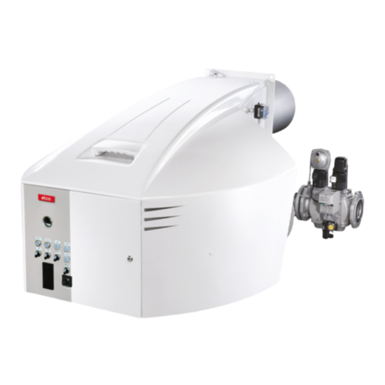
Overview Burner description Power controller (option) Housing Gas inlet flange Burner flame tube Integrated electrical cabinet Burner fixing flange Air intake box Mechanical compound Hoisting eyes Air pressure switch Blower motor Y10 Actuator for air and gas dampers 10/2010 - Art. Nr. 4200 1030 6900A... -
Page 4: Gas Start-Up Mode, Gas Operating Mode
Operation Gas start-up mode Gas operating mode General safety functions Gas start-up mode After the pre-ignition time, the main gas the burner to be operated at any desired As soon as the furnace system is valves are open and the gas comes out stage between its partial-load and full- required to supply heat, the burner from injectors where it is mixed in the... -
Page 5: Fuel-Air Compound Control
Operation Fuel-air compound control Gas valves and instruments group Fuel-air compound control Mechanical compound control: Gas valves and instruments group This compound control system with The compound control system will be The gas valves and instruments group precision-adjustment capability has operated by the steplessly reversible used with the furnace will be selected been designed to allow the fuel and air... -
Page 6: Automatic Furnace Controller Lfl 1
O per at i on A ut om at i c f ur nace cont r ol l er LFL 1. . . / LG K . . . The LFL 1…/LGK... type controller is designed to control and monitor burners working according to a stepwise or modulating principle. -
Page 7: Gas Valve Vgd With Skp Regulator
O per at i on G as val ve VG D w i t h SK P act uat or G as val ve M B C - SE Gas ball valve (option) Filter (under the cover) Gas manometer with push button (upstream) (option) Test burner with push button (option) -
Page 8: Boiler Lining For G-R Burner Burner Assembly
Assembly Boiler lining for G-R burner Burner assembly Boiler lining The burner lining must be installed right- angled to the burner tube. Possible trimming work (bevelling, rounding) as required for reverse boilers, for example, should be done at a diameter not below 70% of the combustion chamber diameter. -
Page 9: Gas Connection
Assembly Gas connection Gas connection Gas connection pressure Leak test A minimum connection pressure must The gas line upstream of the burner gas The gas lines and valves and be available upstream of the burner gas valves and instruments group must be instruments group should be installed valve to ensure the proper functioning of installed in accordance with the... -
Page 10: Checking, Assembling The Combustion Components10
Assembly Checking / assembling the combustion components Burner N6.2400 G-R N6.2900 G-R N7.3600 G-R 234.5 N7.4500 G-R Assembling the combustion components • Check that the O-Ring J1 is in the correct position in the gas elbow. • Check the adjustment settings of the ionisation probe and of the ignition electrode as per the diagrams. -
Page 11: Gas Connection, Electrical Connection
Assembly Gas connection Electrical connection Checks before commissioning General regulations applying to the specified by the draft combustion gas connection ordinance. • The gas train must only be connected It is the responsibility of the fitter or his to the gas mains by a recognised representative to obtain approval for the specialist. -
Page 12: Burner Power Adjusting Sequence
Commissioning Burner power adjusting sequence Setting sequence (short description) Gas pressure setting SQM actuator switch assignment • In electrical cabinet, set switch on "local control / hand" position or Gas train VGD Description Pre setting Function • Adjust min. power switch (minimum •... -
Page 13: Mechanical Compound, Electrical Actuator
C om m i ssi oni ng M echani cal com pound El ect r i cal act uat or Li m i t sw i t ch set t i ng Important A l'issue du réglage des manostats, ceux-ci doivent être protégés contre tout dérèglement. -
Page 14: Monitoring Of The Flame By Ionisation
C om m i ssi oni ng M oni t or i ng of t he f l am e by i oni sat i on Sensor cur r ent m easur em ent Ionisation monitoring During ionisation monitoring, it is Detection of the flame using an important that the signal is transmitted ionisation device. -
Page 15: Gas Pressure Switch Air Pressure Switch
Commissioning Gas pressure switch Air pressure switch Gas pressure switch GW...A5/A6 Gas pressure switch A5 Technical data: The gas pressure switch is designed to monitor the gas flow pressure. It can be Type of gas: used for monitoring either falling Gases according to DVGW Worksheet pressure (minimum) or rising pressure G 260/1, gas families 1, 2, 3... -
Page 16: Description
Gas valves and instruments group Description Specifications for the design, direction of flow (arrow on housing). construction and safety features of gas Prior to installation and operation, check Gas valves and instruments group type furnace systems in heating installations the valves and instruments and the are contained in DIN 4756 and TRD 412. -
Page 17: Basic Construction
Gas valves and instruments groups Basic construction The burner's scope of delivery may Gas trains with a double valve are Low- and high-pressure gas trains include a gas train. In this case, the intended for the supply, main shut-off, If the outlet side of the regulator, i.e. burner and the gas train are issued with gas filtration, gas pressure regulation individual fittings and instruments... - Page 18 Gas valves and instruments groups Basic construction 100 Burner 313 Min. gas pressure switch 101 Impulse pipe gas pressure 314 Gas pressure switch for valve leak check or valve 120 Air flap leak checker 141 Ball valve 349 Actuator 142 Gas filter 144 Gas pressure regulator Options in accordance with country-specific requirements: 145 Safety shut-off valve (SSV)
- Page 19 Gas valves and instruments groups Basic construction Installation and mounting of the gas filter The gas filter may be installed in any desired position. Take care only to observe the direction of flow of the gas (arrow on filter housing). Make sure there is adequate clearance to facilitate the removal of the cover and replacement of the filter cartridge.
-
Page 20: Gas Valve Leakage Controller
Gas valves and instruments group Gas valve leakage controller Leakage controller VPS 504 S02 Working principle : Prior to each burner start-up, the controller checks for possible leaks between safety and main valves by increasing distribution pressure. Electrically, the leakage controller is serially connected between the thermostatic circuit and burner control and safety unit. -
Page 21: Maintenance
Servicing Maintenance Burner and boiler servicing must only Work recommended as part of annual - Flame monitor and automatic be carried out by a professionally burner maintenance: combustion control unit function check qualified heating engineer. The system - Burner test run, input measurement in - Commissioning the burner operator is advised to take out a the boiler room... - Page 22 Servicing Maintenance Filter replacement Checking the flue gas temperature • The filter element of the must be Precautions • Check the flue gas temperature at checked at least once a year and After any operation: check the regular intervals. replaced if clogged. combustion performance under real •...
-
Page 23: Exhaust Gas Test Trouble Shooting Instructions
Servicing Exhaust gas test Trouble shooting instructions Exhaust gas loss Natural Town Exhaust gas loss by way of free heat will L.P.G. occur as a result of the temperature difference between the fuel-air mixture 0,370 0,350 0,420 entering the furnace chamber and the 0,009 0,011 0,008... - Page 24 Servicing Exhaust gas test Trouble shooting instructions 6. Cleaning and lubricating 4. Mixing unit gives poor 5. Solenoid valve fails to open instructions combustion data Depending on the amount of dirt Cause Remedy introduced by the combustion air it will Cause Remedy Defective coil or...
-
Page 25: Operating Trouble
Servicing Operating trouble In case of operating trouble it should 3. Proper functional order and setting of Proceed with searching for the cause of be checked whether the system is in all control and safety instruments the trouble and eliminate it. Unlock the proper working order. - Page 26 10/2010 - Art. Nr. 4200 1030 6900A...
- Page 27 10/2010 - Art. Nr. 4200 1030 6900A...
- Page 28 Hotline ELCO Austria GmbH Aredstr.16-18 0810-400010 2544 Leobersdorf ELCO Belgium nv/sa Z.1 Researchpark 60 02-4631902 1731 Zellik ELCOTHERM AG Sarganserstrasse 100 0848 808 808 7324 Vilters ELCO GmbH Dreieichstr.10 0180-3526180 64546 Mörfelden-Walldorf ELCO Italia S.p.A. Via Roma 64 800-087887 31023 Resana (TV) ELCO Burners B.V.
Need help?
Do you have a question about the N6.2400 G-R and is the answer not in the manual?
Questions and answers