Table of Contents
Advertisement
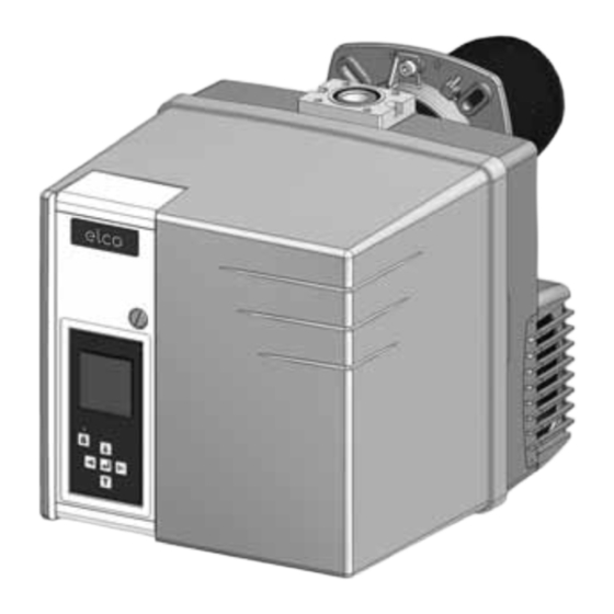
VG 2.210 V
Operating instructions
For specialist installation engineers
Gas burners ........................................... 2-31
de, fr..................................... 4200 1053 2700
it, nl ...................................... 4200 1053 2800
............................................. 4200 1053 2600
09/2013 - Art. Nr. 4200 1053 2900A
en
Advertisement
Table of Contents
Troubleshooting

Related Manuals for elco VG 2.210 V


Summary of Contents for elco VG 2.210 V
- Page 1 VG 2.210 V Operating instructions For specialist installation engineers Gas burners ........... 2-31 de, fr........4200 1053 2700 it, nl ........4200 1053 2800 ..........4200 1053 2600 09/2013 - Art. Nr. 4200 1053 2900A...
-
Page 2: Table Of Contents
Fault diagnosis menu, Operating statistics menu........30-31 Important information 1 Bag containing mounting parts VG 2.210 V burners are designed for the 1 Bag containing Technical low-pollutant combustion of natural gas Documentation and propane gas. The design and... -
Page 3: Burner Description
Overview Burner description Control and safety unit Display Air pressure switch Blower motor Igniter Y10 Air flap servomotor Frequency converter for speed control Adjusting screw for dimension Y Sealing washer for Liquefied Petroleum Gas Housing Plate hanging device (Maintenance) Burner tube 7-pin connector 10.1 4-pin connector 10.2 3-pin connector (auxiliary motor... -
Page 4: Description Of The Function Safety Functions
Operation Description of the function Safety functions Description of the function Safety functions A pre-ventilation time of 24 seconds - If no flame is produced when the begins when first powering up, after a burner is started (gas release), the burner is switched off at the end of the power cut or a lockout, after the gas safety time which lasts no more than... -
Page 5: Control And Safety Unit
Operation TCG 8xx control unit Locking and unlocking The TCG 8xx control and safety unit controls and monitors the forced draught The control unit can be locked (switched burner. The microprocessor-controlled to malfunction mode) by pressing the program sequence ensures maximum unlocking button and unlocked (fault stability of time periods, regardless of... - Page 6 • menu for setting/ modifications may be adjusting the standard carried out on-site configurations* without prior consultation with ELCO. The access code and the setting setpoints for these menus are available on request. 09/2013 - Art. Nr. 4200 1053 2900A...
- Page 7 Operation TCG 8xx control unit Operating cycle phases: 13:Closing of the air flap until the 1: No voltage minimum regulation position is 2: Powering up, no heat request reached 3: Heating request 14:Operation at intermediate regulation 4: Opening an air flap, arrival in pre- power ventilation position 15:Operation at minimum regulation...
-
Page 8: Terminal Allocation Chart, Connection Socket
Operation Terminal allocation chart 230 Volt connection Control thermostat Heating L1 power Solenoid valve Earth Earth Burner motor Igniter request supply Connector Terminal Flame check Air pressure Remote Fault Gas pressure switch unlocking display switch Connector Terminal Terminal Description Connector Terminal Description Connector... - Page 9 Operation Terminal allocation chart Low voltage connections Display-PC interface Terminal Connector Connector Terminal Speed converter Air servomotor Terminal Description Connector Terminal Description Connector not used not used not used not used not used not used not used not used not used not used not used not used...
-
Page 10: Mb-Vef Gas Train
Operation MB-VEF gas train Electrical connection of solenoid valves (DIN 43650) Electrical connection of the gas pressure switch (DIN 43650) Gas pressure switch Inlet flange Pressure measuring nipple R1/8, upstream of filter (option) Filter (under the cover) Connection for furnace pressure release pipe pF, R1/8 Adjusting screw for V ratio Adjusting screw for zero point... -
Page 11: Burner Assembly
Assembly Burner assembly Burner assembly Installation: Burner flange 3 is equipped with • Secure connecting flange 3 to the boiler using screws 4 elongated holes and can be used with a • Fit pipe bracket 2 to the burner pipe hole circle diameter of 150 - 184mm. -
Page 12: Gas Train, Pressure Take-Off Pipes
• Route the connection cable for the gas train through clamp 7 and connect it to the gas train. On burners VG 2.210 V, fit the restricting piece 2 (comes with gas train fittings bag, with the burner flange. -
Page 13: Checking The Mixing Unit
Assembly Checking the mixing unit Checking the mixing unit • Loosen the three cover screws W. • Remove the cover. • Loosen lock nut E on the gas pipe bracket • Loosen the retaining bolt. • Remove the mixing unit. Setting to liquid gas operation •... -
Page 14: Electrical Connection, Testing Before Commissioning
Assembly Electrical connection Checks before commissioning Ionisation current measurement General regulations applying to the specified by the draft combustion gas connection ordinance. • The gas train must only be connected It is the responsibility of the fitter or his to the gas mains by a recognised representative to obtain approval for the specialist. -
Page 15: Adjustment Data
Commissioning Adjustment data Burner Dimension Frequency converter Gas valve setting Air flap setting power setting Screw V / Screw N (mm) Parameter MB-VEF412 MB-VEF407 Mini. Maxi. Ignition Mini. Maxi. 2 / -1 VG 2.210V 25*/35** 2,5 / -1 2,5 / -1 2,5 / 0 2,5 / 0 2,5 / -2... -
Page 16: Air Regulation Gas Valve Adjustment
Commissioning Air regulation Gas valve adjustment The combustion air is regulated via The regulation of air in the burner head three parameters: affects not only the air flow but also the • On the pressure side by means of the mixing zone and the air pressure in the burner tube. -
Page 17: Pre-Adjustment Without Flame, General Advice Before Starting The Burner
Commissioning Pre-setting without flame Important Setting is carried out in 2 phases: - pre-adjustment without flame At this point, no setting position for the - setting the flame, to fine tune the servomotor has been defined, therefore settings based on the combustion the burner cannot be started under results these conditions. -
Page 18: Before Starting The Burner
Commissioning Pre-setting without flame General advice before starting the burner End of presetting menu without flame When all the positions of the servomotor have been determined according to the required settings, it is then possible to move on to the next section for commissioning - "Setting the flame". To do this, place the cursor in the lower part of the screen on the symbol and confirm by pressing the... -
Page 19: Setting The Flame
Commissioning Setting the flame - If the boiler heating request The air flap switches to the is not present, the boiler ignition/pre-ignition position. remains on standby. In this case, it is still possible to return to the previous setting menu "Pre-setting without flame". - Page 20 Commissioning Setting the flame Setting the minimum pressure If the flame has been detected and stabilised, the control unit sets the burner to minimum power as soon as it receives the regulation authorisation. , soot test). If necessary, adjust screw N on the valve - Check the combustion values (CO, CO (see page16).
- Page 21 Commissioning Setting the flame Operating mode Closing the "Setting the flame" menu The burner setting is now complete. If necessary, it is possible to again correct each of the settings values. To do this, position the cursor on the value to be modified, using the key.
-
Page 22: Air Regulation
Commissioning Air regulation Air regulated via frequency converter Example: The operating speed of the fan must The fan speed is controlled via the not exceed 50 Hz. frequency converter, depending on the position of the air damper. The minimum and maximum fan speed are set via the LL and UL parameters as a frequency (50 Hz ~ 2800 U/min). - Page 23 Commissioning Air regulation Setting the LL and UL parameters For the operation VG 2.210 V, all parameters are pre set at the factory, so that it’s only necessary, without exception, to adjust the settings LL, UL parameters. Abstract of parameters list Only are represented the parameters required for the operation of the burner, as well as those who differ from the pre factory settings provided by the manufacturer.
-
Page 24: Setting The Gas Pressure Switch, The Air Pressure Switch
Commissioning Setting the gas pressure switch Setting the air pressure switch Saving the adjustment values in the display Setting the gas pressure switch • Turn the dial clockwise until the gas • To set the switch-off pressure: remove pressure switch shuts down the the cover from the gas pressure burner. -
Page 25: Maintenance
Servicing Maintenance Burner and boiler servicing must only be Work recommended as part of annual - Flame monitor and automatic carried out by a professionally qualified burner maintenance: combustion control unit function check heating engineer. The system operator is - Burner test run, input measurement in - Commissioning the burner advised to take out a maintenance the boiler room... - Page 26 Servicing Maintenance Replacing the flame tube Cleaning the cover It is necessary to remove the burner for • Do not use abrasive products or this work. products containing chlorine. • Loosen the clamping screw on the • Clean the cover with water and a connecting flange.
-
Page 27: Troubleshooting
Servicing Troubleshooting Malfunction diagnosis and repair Only use original spare parts. Switch off the power supply In the event of a malfunction, first check before carrying out that the prerequisites for correct operation are fulfilled: maintenance or cleaning. 1. Is there any current? After any work on the system: 2. -
Page 28: Troubleshooting
Servicing Troubleshooting Symbol Observation Cause Corrective action Burner blower starts up. Air pressure switch: Contact does Readjust the pressure switch. Burner does not start. not close. Check the wiring. Replace the pressure switch. Burner blower starts up. Flaring during pre-ventilation or Check the valve. -
Page 29: Maintenance / Troubleshooting Of The Frequency Converter
Servicing Maintenance Troubleshooting of the frequency converter Maintenance The converter does not require any preventive maintenance. However, the following should be performed at regular intervals: - check the condition and tightness of the connections, - ensure that the temperature in proximity to the device is acceptable, and that there is adequate ventilation (average service life of blowers: 3 to 5... -
Page 30: Fault Diagnosis Menu Operating Statistics Menu
Servicing Fault diagnosis menu Operating statistics menu Fault diagnosis menu To access the fault diagnosis menu, press any key when the burner is ready to operate, when the burner is in operation, or when it is in malfunction mode. It is not possible to access the fault diagnosis menu during the start-up phase. - Page 31 Servicing Operating statistics menu - Total number of burner start-ups since the last meter reset - Total number of faults since the last meter reset - Total operating time since the last meter reset - Total number of operating hours at rated output since the last meter reset - Number of "unwanted flame"...
- Page 32 Made in EU. Non contractual document. 09/2013 - Art. Nr. 4200 1053 2900A...
Need help?
Do you have a question about the VG 2.210 V and is the answer not in the manual?
Questions and answers