Table of Contents
Advertisement
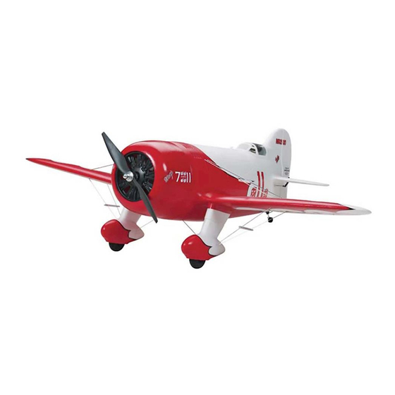
Wingspan: 68 in [1727mm]
Wing Area: 743 sq in [48 dm
Weight: 11-1/4 - 12-1/4 lbs [5103 - 5557 g]
Wing Loading: 34.9 - 38 oz/sq ft [106 - 116 g/dm2]
Length: 45 in [1143mm]
Radio: 4 channel with six servos
Engine: .91 - 1.08 cu in [15cc - 18cc] two-stroke,1.20 cu in [20 cc] four-stroke
Great Planes
®
Model Manufacturing Co. guarantees this kit to be free from defects in both material and workmanship at the date of
purchase. This warranty does not cover any component parts damaged by use or modification. In no case shall Great Planes' liability
exceed the original cost of the purchased kit. Further, Great Planes reserves the right to change or modify this warranty without notice.
In that Great Planes has no control over the final assembly or material used for final assembly, no liability shall be assumed nor
accepted for any damage resulting from the use by the user of the final user-assembled product. By the act of using the user-assembled
product, the user accepts all resulting liability.
If the buyer is not prepared to accept the liability associated with the use of this product, the buyer is advised to return this
kit immediately in new and unused condition to the place of purchase.
READ THROUGH THIS MANUAL BEFORE
STARTING CONSTRUCTION. IT CONTAINS
IMPORTANT WARNINGS AND INSTRUCTIONS
CONCERNING THE ASSEMBLY AND USE OF
THIS MODEL.
© Copyright 2003
INSTRUCTION MANUAL
]
2
WARRANTY
Champaign, Illinois
(217) 398-8970, Ext 5
airsupport@greatplanes.com
GPMZ0282 for GPMA1326 V1.0
Advertisement
Table of Contents

Related Manuals for GREAT PLANES Gee Bee


Summary of Contents for GREAT PLANES Gee Bee
-
Page 1: Instruction Manual
Further, Great Planes reserves the right to change or modify this warranty without notice. In that Great Planes has no control over the final assembly or material used for final assembly, no liability shall be assumed nor accepted for any damage resulting from the use by the user of the final user-assembled product. -
Page 2: Table Of Contents
Fuel Mixture Adjustments..........32 IMPORTANT SAFETY PRECAUTIONS Takeoff ................33 Flight.................33 1. Your Gee Bee should not be considered a toy, but rather a Aerobatics ................33 sophisticated, working model that functions very much like a full- Engine Out Situation ............33 size airplane. Because of its performance capabilities, the Gee Landing................33... -
Page 3: Safety Precautions
(fuel tank, wheels, etc.) throughout the building process. This is a partial list of items required to finish the Gee Bee 5. You must correctly install all R/C and other components so that may require planning or decision making before starting that the model operates correctly on the ground and in the air. -
Page 4: Decisions You Must Make
2 oz. [57g] spray CA activator (GPMR6035) • The Gee Bee is factory-covered with Top Flite MonoKote CA applicator tips (HCAR3780) film. Should repairs ever be required, MonoKote can be patched CA debonder (GPMR6039) with additional MonoKote purchased separately. -
Page 5: Ordering Replacement Parts
ORDERING REPLACEMENT PARTS To order replacement parts for the Great Planes Gee Bee ARF, use the order numbers in the Replacement Parts List that follows. Replacement parts are available only as listed. Not all parts are available separately (an aileron cannot be purchased separately, but is only available with the wing kit). -
Page 6: Kit Contents
If any parts are missing or are not of acceptable quality, or if you need assistance with assembly, contact Product Support. When reporting defective or missing parts, use the part names exactly as they are written in the Kit Contents list on this page. Great Planes Product Support 3002 N. Apollo Drive, Suite 1 Champaign, IL 61822... -
Page 7: Preparations
ASSEMBLE THE FUSELAGE STAND Because of the awkward shape of the Gee Bee we have designed a very useful foam cradle for the model. As you have already seen it was used in the shipping box,... -
Page 8: Build The Wing
5. Remove any pins you may have inserted into the BUILD THE WING hinges. Adjust the aileron so there is a small gap between the LE of the aileron and the wing. The gap should be small, just enough to see light through or to slip a piece of paper through. Install the Ailerons Do the right wing first so your work matches the photos the first time through. -
Page 9: Install The Aileron Servos And Pushrods
3. Tie the string from inside the wing to the end of the 9. On the top of the wing, cut the covering away from servo wire. Pull the servo wire through the wing with the the hole at the wing center section. This hole is for the string. -
Page 10: Join The Wings
servo. Mark the location for the screw holes. Drill through the Join the Wings marks you made with a 1/16" [1.6mm] drill bit. (Be sure you are drilling into the plywood plate mounted in the bottom of the aileron. Drill through the plate only. Do not drill all the way through the aileron!) Using a #2 x 1/2"... -
Page 11: Install The Landing Gear
photo, mark the location for the screw holes. Note: It is important that the straps are located as shown or they could interfere with the installation of the wheel pants. Drill a 1/16" [1.6mm] hole through the marks, drilling through the hardwood rail under the covering. - Page 12 8. Locate two 1/8" x 3/8" x 3/8" [3mm x 51mm x 51mm] 5. Position the wheel pant so that the wheel is plywood plates. From one edge of the plate measure in centered in the opening. Mark four locations for the wheel 7/8"...
-
Page 13: Install The Belly Pan
sanding, clean the area with rubbing alcohol. Mix 1/4 ounce Install the Belly Pan [2 drams] of 6-minute epoxy and some microballoon filler. Add enough filler to make it difficult for the epoxy to run. Glue the plates inside each of the wheel pants, referencing the marks you made. -
Page 14: Assemble The Fuselage
4. 1/16" [1.6mm] inside the lines you have drawn cut a 3/4" 5. Where the belly pan contacts the wing, sand the inside [19mm] wide strip of covering from the wing. Use a sharp #11 of the belly pan with 220-grit sandpaper and then wipe the hobby knife or use the Expert Tip that follows to cut the residue clean with rubbing alcohol. - Page 15 Even with the extension it will be necessary to make a small clearance opening in the bottom of the fuselage to allow clearance between the muffler and the fuselage. Depending 2. Position your engine onto the engine mount. Position on the brand of engine used, you may have to change the the engine on the mount so that the distance from the back position of this clearance hole.
- Page 16 four #8 lock washers, four #8 flat washers and Thread-Lock. (Depending on your engine, you may have to remove the engine from the engine mount before installing the mount to the firewall. If this is the case with your engine, re-install the engine to the mount after the mount is attached to the fuselage).
-
Page 17: Install The Fuel Tank
2-56 (.074") Pushrod Wire Servo Horn FasLink RETAINER 15. Cut off the threaded portion of a 6" [13mm] wire pushrod. Make a 90 degree bend on the end of the wire leaving 3/16" [4.8mm] extending from the bend. Install a brass quick connect onto the throttle arm using the nylon retainer. -
Page 18: Install The Cowl Ring, Cowl And Dummy Engine
Dummy Engine You may already have discovered that the Gee Bee stands on its tail pretty well. For the installation of the cowl you will find it helpful to stand the fuselage on its tail. - Page 19 Glue the tabs to the firewall with 5-minute epoxy. Align the line center of the tab. On the mark, drill through the ring and the on each tab with the edge of the firewall. After the glue has mounting tab with a 1/16" [1.6mm] drill bit. Remove the clamp cured drill two 1/16"...
- Page 20 12. Cut a hole in the center of the dummy engine large 15. Paint the dummy engine with a fuel proof paint. Paint enough to clear the thrust washer of the engine. Position the the cylinders and the area around them flat black and the dummy engine over the engine.
- Page 21 22. With the fuselage standing on its tail, place the dummy 17. Place the cowl onto the ring, centering the cowl on engine over the engine. Then place the cowl over the dummy the engine. Do not push the cowl onto the cowl mounting engine.
-
Page 22: Mount The Stab, Elevator, Rudder And Tailwheel
Mount the Stab, Elevator, Rudder and Tailwheel 1. Temporarily install the wing onto the fuselage with two 1/4-20 nylon wing bolts. 2. Trial fit the horizontal stabilizer into the stabilizer saddle at the rear of the fuselage. You may find it necessary to sand inside the stabilizer saddle to remove any excess fiberglass resin that may have accumulated in the molding process. - Page 23 13. Trial fit the rudder by sliding the rudder onto the tailwheel wire. The nylon bearing should fit into the slot you have cut in the rudder. Adjust the slot as needed until the leading edge of the rudder is in contact with the trailing edge of the fuselage.
-
Page 24: Install The Elevator And Rudder Servos, Radio System
under the covering. Use a pin to determine that you have located the hardwood plate. Important! This is the bottom of the elevator. The control horns mount to these plates and when installed properly the plates are on the bottom of the elevator. - Page 25 6. On the left side of the fuselage below the stab are located two molded pushrod exit locations. Cut them out. On the right side of the fuselage is located one molded pushrod exit. Cut it out as well. 11. Insert the wire into the hole in the dowel. Glue the wire to the groove with a small amount of medium CA.
- Page 26 18. Repeat steps 7 - 17 to make a second, matching pushrod. 26. From the ends of the dowel to the holes make grooves. 19. Install a clevis and silicone clevis keeper to the 27. On the non-threaded end of the 6-1/2" [165mm] wire threaded end of the wire the same as was done with the ailerons.
- Page 27 Install a 12" aileron extension to the receiver for the ailerons. 38. Mount the receiver on/off switch. A Great Planes Switch & Charge Jack Mounting Set (GPMM1000, not included) was used on this model. Be certain it is in a location away from engine exhaust.
-
Page 28: Finishing Touches
wing and the aileron. Note: The bottom of the wing has the Finishing Touches same decals as the top but the N-number is on the left side and the number “7” is on the right. 1. Paint the pilot and install it in the cockpit area. 5. -
Page 29: Set The Control Throws
Set the Control Throws This is where your model should balance. For the Gee Bee we do not recommend that you move the C.G. forward or back from this point. In our testing we found that moving the C.G. -
Page 30: Balance The Model Laterally
“spinner weight” (GPMQ4645 for the 1 oz. weight, or GPMQ4646 for the 2 oz. weight). If spinner weight is not practical or is not enough, use Great Planes (GPMQ4485) Follow the battery charging instructions that came with your “stick on” lead. A good place to add stick-on nose weight is to radio control system to charge the batteries. -
Page 31: Engine Safety Precautions
We use a Top Flite Precision Magnetic Prop Balancer ™ (TOPQ5700) in the workshop and keep a Great Planes Keep these items away from the prop: loose clothing, shirt Fingertip Prop Balancer (GPMQ5000) in our flight box. -
Page 32: Checklist
Many are covered in the instruction manual, The Gee Bee is a great-flying model that flies smoothly and so where appropriate, refer to the manual for complete predictably. The Gee Bee does not, however, possess the instructions. -
Page 33: Takeoff
Mind your fuel level, but use this first flight to become Takeoff familiar with your model before landing. This is a Gee Bee and the Gee Bee has had a reputation for Aerobatics being a difficult airplane to fly but we have designed many of the bad flight characteristics out of the model. - Page 34 Remember to think. control. You can also land the Gee Bee on the main wheels and execute a slightly longer roll out with the tail off of the Have a ball! ground.
Need help?
Do you have a question about the Gee Bee and is the answer not in the manual?
Questions and answers