Table of Contents
Advertisement
Quick Links
PLEASE READ THROUGH THIS INSTRUCTION BOOKLET IN ITS ENTIRETY BEFORE BEGINNING
ASSEMBLY. IT CONTAINS IMPORTANT INSTRUCTIONS AND WARNINGS CONCERNING THE ASSEMBLY
AND USE OF THIS MODEL.
This R/C kit and the model you will build is not a toy! It is capable of serious bodily
harm and property damage. IT IS YOUR RESPONSIBILITY AND YOURS ALONE - to build
this kit correctly, properly install all R/C components and to test the model and fly it only with
experienced, competent help in accordance with all safety standards and common sense as set
down in the Academy of Model Aeronautics Safety Code. It is suggested that you join the AMA
to become properly insured before you attempt to fly this model. IF YOU ARE JUST START-
ING R/C MODELING, CONSULT YOUR LOCAL HOBBY SHOP OR WRITE TO THE
ACADEMY OF MODEL AERONAUTICS TO FIND AN EXPERIENCED INSTRUCTOR IN
YOUR AREA.
Academy of Model Aeronautics
5151 Memorial Drive
Muncie, IN 47302
INSTRUCTION BOOK
WARNING! THIS IS NOT A TOY!
1-800-435-9262
P.O. BOX 788
URBANA, ILLINOIS 61801
217398-8970
Advertisement
Table of Contents

Related Manuals for GREAT PLANES Spirit GPMA0530


Summary of Contents for GREAT PLANES Spirit GPMA0530
- Page 1 INSTRUCTION BOOK PLEASE READ THROUGH THIS INSTRUCTION BOOKLET IN ITS ENTIRETY BEFORE BEGINNING ASSEMBLY. IT CONTAINS IMPORTANT INSTRUCTIONS AND WARNINGS CONCERNING THE ASSEMBLY AND USE OF THIS MODEL. WARNING! THIS IS NOT A TOY! This R/C kit and the model you will build is not a toy! It is capable of serious bodily harm and property damage.
-
Page 2: Table Of Contents
If you are calling for replacement parts, please look up the part numbers and the kit identification number (stamped on the end of the kit box) and have them ready when calling. Thank you. Great Planes Model Mfg., Inc. P.O. Box 788... -
Page 3: Introduction
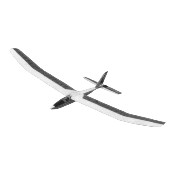
BB's or Lead Shot for Balancing and cover many miles at incredible altitudes. The Optional Spoilers Also Require: Thank you for purchasing the Great Planes SPIRIT 3/16" x 1/4" x 36" Balsa Stick sailplane. It has been designed to give you many hours of 30"... -
Page 4: Die Patterns
DIE PATTERNS Do not punch out die-cut parts until ready to use! 2 PER KIT SPRTFO1 BALSA 3/32" X 3-1/4" X 38-1/2" SPRTF02 2 PER KIT 1 PER KIT SPRTF06 REAR FUSELAGE DOUBLER FRONT FUSELAGE DOUBLER BALSA 1/8" X 3" X 9-7/8" BALSA 3/32"... -
Page 5: Abbreviations
COMMON ABBREVIATIONS USED IN TYPES OF WOOD THIS BOOK AND ON THE PLANS: Elev Elevator Fuse Fuselage Leading Edge (front) Left Plywood Right Stabilizer Stab B A S S W O O D P L Y W O O D BALSA Trailing Edge (rear) "... -
Page 6: Tail Feathers
"TAIL FEATHERS" BUILD THE FIN AND RUDDER You'll need the following parts: SPRTS02 3/16" x 3/8" x 30" Balsa Stick SPRTS03 1/8" x 3/16" x 30" Balsa Stick SPRTS01 3/16" Die-Cut Tail Parts D 4. Remove the fin and rudder assemblies from the plan SPRTF08 3/16"... -
Page 7: Build The Stabilizer And Elevator
D 1. Tape waxed paper over the stabilizer drawing on the plan. In the same manner as the rudder, cut the 3/16" x 3/8" balsa pieces and using the die-cut Stab Tips, Stab Center and Stab Brace from SPRTS01, assemble the stab frame- work using thin CA glue. -
Page 8: Cut The Hinge Slots
D 6. Remove the elevator and draw a center line down its leading edge. Use your sanding block to sand the same V- D 2. Draw accurate centerlines down the trailing edge of shape as you did on the rudder. The trailing edge should also the stab and the fin. -
Page 9: Wing Assembly
D 4. Carefully punch out all the die-cut 1/16" Balsa W2 WING ASSEMBLY and W2S Wing Ribs. Sand the edges slightly to remove any die-cutting irregularities. BUILD THE INNER WING PANELS NOTE: Follow step 5 below through step 7 on page You'll need the following parts: 15 to build the LEFT wing panel, then repeat these steps to build the RIGHT wing panel. - Page 10 edges are NOT symmetrical. Refer to one of the section views on the plans to determine which way they should be installed. Carefully hold the leading edge against one of the end W-2 ribs and note that it is wider than the front of the rib. This is because the 1/16"...
- Page 11 in the first three rib "bays". NOTE: if you are installing spoilers in the wing or may add them in the future, install the web between the two W2S ribs on the FRONT of the spars to make room for the spoiler horn. IF YOU ARE BUILDING A ONE-PIECE WING, SKIP AHEAD TO "BUILD THE OUTER WING PANEL"...
-
Page 12: Build The Outer Wing Panel
Shaped 1/16" balsa DD 1. Lay one of the Outer Trailing Edges balsa LE bottom sheet 1/16" (SPRTW 12) in place over the plan and cut it to length just past Spars balsa the last notch. Align the notches in the trailing edge with the scrap notches on the plans and pin it in position. - Page 13 DD 11. Glue the 7/8" x 1-1/4" x 6-1/4" Tapered Wing Tip Blocks (SPRTW15) to W10 with thick CA. The sketch DD 6. Carefully bend the leading edge to the angle below and the cross sections on the plan shows how the block shown on the plans and position it against the ribs.
-
Page 14: Join The Wing Panels
sand the leading edge, spars and trailing edge so they are all even and of the correct length. NOTE: The SPIRIT'S wing is designed to be just under the legal maximum projected wing span for 2-meter sailplanes (approximately 78-3/4"). Be very careful when joining these panels to get the right amount of dihedral and to keep the panels the correct length or you DD 13. -
Page 15: Final Wing Assembly
D 2. Use either epoxy or thick CA to glue one of the 1/16" laminations to the 1/8" laminations. Apply as much pressure (clamps, clothespins, weights, etc.) as possible while the glue is curing and be sure to accurately line up the two pieces. Next, glue this lamination assemby and the other 1/16"... - Page 16 place using thick CA. It should be centered (up and down) on the leading edge because 1/16" sheeting will be added later. D 6. Punch out all four of the Wing Joiner Laminations, the Dihedral Braces and the Leading Edge Brace from the die-cut sheets SPRTW04 and SPRTW05.
- Page 17 -Cut W1A Rib and Leading Edge Sheeting away to clear Nylon Wing Bolt and act as a lunge for the gluing process. Press the sheeting into place and trim it flush with the back edge of the spar using a modeling knife and straightedge. D 14.
- Page 18 D 23. With the spoiler in place, glue the 3/16" x 1/4" x 1-1/4" pieces of balsa to ribs W2. These are the spoiler rests and should be positioned so they hold the spoiler flush with the top surface of the wing. NOTE: It is important that the spoiler sit flush with the top of the wing or it will unneces- IF YOU ARE NOT INSTALLING sarily disrupt the airflow over the wing.
-
Page 19: Fuselage Assembly
these sheets to match the contour of the wing and be careful not to add much to the wingspan with these extra sheets. D 30. Sand three edges (two short and one long edge) of each 1/16" Plywood Wing Protector (SPRTW18) to a taper as shown on the plans and glue them in place on top of each trailing edge. -
Page 20: Frame-Up The Fuselage
FRAME-UP THE FUSELAGE DD 3. Glue the 3/32" Die-Cut Balsa Rear Fuselage Doubler (SPRTF02) in place making sure it lines up with the fuselage sides at the rear of the doubler where the arrows in the photo arc pointing. D 1. Lay a piece of waxed paper over the FUSELAGE TOP VIEW. - Page 21 joints and around former F6. Take your time apply ing the thin CA and be sure to get the bottom and the sides pressed together nicely. Thick CA can then be added to these joints to add strength. fuselage bottom with thick CA. Use the fuselage sides to help position it.
- Page 22 These pieces should be glued with thick CA. They are pressed into the corner between the fuselage bottom and the fuselage doubler in the following places: Glue the 4-5/8" pieces behind the towhook plate. Glue the 2" long pieces on top of and in front of the towhook plate.
-
Page 23: Assemble The Canopy
D 14. Insert the 1/4" wing dowels in the holes in the fuselage and temporarily rubber band the wing in position on the fuselage and use a string as shown in the sketch to make sure it is on straight. Make a couple of marks on the wing and fuse to help you make sure it stays in position while drilling the wing bolt holes. - Page 24 D 6. The canopy may have a Plastic Film on either or both sides. Check for this and remove it if you find one. Tint the Canopy (CANPY044) if you wish, using powdered clothing dye that you can buy at the grocery store (Rit, etc). Use very warm water (warmer than you can leave your hand in) but do not use very hot water or the canopy may deform.
-
Page 25: Final Assembly
merit and wedge the other one between the sides in the weight plane fore and aft". That very important step compartment. These pieces arc called the Canopy Aligners. will be covered later in the manual. Lift the aligners so that they are slightly above the sides. Apply a small drop of thick CA to the middle of each aligner Now that you have the basic airframe nearly completed, and carefully slide the canopy into place. -
Page 26: Checking For Warps
• Work outward, start by tacking the covering in place at the 17. Top of left wing panels (overlap covering l/4"at LE comers and then start in the middle and work your way out to and TE) the comers, gently pulling any wrinkles out as you go. Top of right wing panels (overlap covering 1/4"... -
Page 27: Mount The Tail Surfaces
place on the rudder and elevator with a drop of thin CA. Use them into place (up to the middle of the hinge) and wipe away the plans as a reference for positioning the horns (Rudder on all excess epoxy with a tissue (for best results dampen the the left, elevator on the bottom). -
Page 28: Install Radio Gear
pushrod. Tack glue the wires in place with a couple drops of two servo horns you cut earlier with the arms facing opposite CA. Firmly wrap the end of the pushrod with strong thread directions as shown on the plans. Operate the transmitter and apply thick CA to hold everything in place as shown on sticks to make sure the servo horns turn freely without hitting the plans and in the photo. -
Page 29: Control Throws
D 8. Pack the receiver in at least 1/4" of foam and install INSTALL THE SPOILERS IN THE WING it in between formers F3 and F4. If you are installing spoilers, (OPTIONAL) mount the receiver behind the rudder and elevator servos. The receiver antenna can run down through the fuselage but try to route it as far away from the servos and servo wires as D 1. -
Page 30: Final Hookups And Checks
let it gain excessive speed. If it does tuck under and you have plenty of altitude, give the plane a little down elevator and RADIO SET-UP allow it to go on under. When it starts to climb up the back of the "outside loop"... -
Page 31: Pre-Flight
PRE-FLIGHT band the wing to the fuselage using eight (8) #64 rubber bands. If you built a bolt-on wing. Use two 1/4 - 20 nylon bolts to hold the wing in place. Cut the bolts to the proper length so they will not interfere with the controls inside the CHARGE THE BATTERIES fuselage. -
Page 32: Flying
down. With the nose pointed down slightly the sailplane will FLYING accelerate down until it picks up enough flying speed then level off and glide forward. The plane should be launched with a gentle push forward. With a little practice you will be able to launch it just the right speed so it soars straight ahead in a long and impressive glide path. -
Page 33: First Flights
Follow the directions that came with the hi-start and lay it Don't worry about accomplishing very much on your first out directly into the wind. Place the stake at the far upwind flights. Use these flights to get the "feel" of the controls and the SPIRIT'S flying characteristics. -
Page 34: Thermal Soaring
5,000 feet per minute (that's over 50 miles/hour straight up!) THERMAL SOARING These strong thermals can rip a plane apart or carry the plane out of sight before the pilot can get out of the updraft Thermals are formed by the uneven heating of the earth It takes a lot of concentration to thermal soar effectively. -
Page 35: Pointers For Contest Flying
spin that will not over stress the airframe but it will enable it gusts and dump the extra altitude and speed at the last second. to lose altitude very quickly. This is especially helpful if the They can also be used to help control your skid. Opening the sailplane gets sucked into a cloud or it gets too high to see. -
Page 36: Slope Landings
To fly off a slope, stand near the edge and throw the weight of your sailplane does not directly change its "glide sailplane (nose down) into the wind. As the sailplane flys out ratio'' but it does make it fly faster which makes it sink a pro- into the "band*' of lift it will begin to gain altitude. -
Page 37: Parts List
PARTS LIST PART # QTY. DESCRIPTION PART # QTY. DESCRIPTION PACKED LOOSE IN KIT SUB-PACK LONG STICKS (Cont.) CANPY044 1 SPIRIT Canopy SPRTF08 3/16" x 24" Balsa Triangle SPRTD01 SPIRIT Decal Sheet SPRTF09 1/4" Square x 18" Balsa SPRTF10 Shaped Balsa Nose Block Pushrod SPRTF12 ABS Formed Cockpit... - Page 38 CONTEST PRACTICE RECORD Use this chart to record your contest practice flying and watch your flying improve! Target Time Flight Time Landing Distance Landing Distance Date Date Target Time Flight Time (Minutes) (Min. : Sec.) (Distance from Spot) (Distance from Spot) (Minutes) (Min.
-
Page 39: Contest Practice Chart
CONTEST PRACTICE RECORD Use this chart to record your contest practice flying and watch your flying improve! Landing Distance Flight Time Landing Distance Date Target Time Flight Time Date Target Time (Distance from Spot) (Min. : Sec.) (Distance from Spot) (Minutes) (Min. -
Page 40: 2-View Drawing
2 - VIEW DRAWING Use this drawing to plan your trim scheme...
Need help?
Do you have a question about the Spirit GPMA0530 and is the answer not in the manual?
Questions and answers