Table of Contents
Advertisement
®
Great Planes
Model Manufacturing Co. guarantees this kit to be free from defects in both material and
workmanship at the date of purchase. This warranty does not cover any component parts damaged by use or
modification. In no case shall Great Planes' liability exceed the original cost of the purchased kit. Further, Great
Planes reserves the right to change or modify this warranty without notice.
In that Great Planes has no control over the final assembly or material used for final assembly, no liability shall be
assumed nor accepted for any damage resulting from the use by the user of the final user-assembled product. By the
act of using the user-assembled product, the user accepts all resulting liability.
If the buyer is not prepared to accept the liability associated with the use of this product, the buyer is advised
to return this kit immediately in new and unused condition to the place of purchase.
While this kit has been flight tested to exceed normal use, if the plane will be used for extremely high stress flying, the
modeler is responsible for taking steps to reinforce the high stress points.
READ THROUGH THIS MANUAL BEFORE
STARTING CONSTRUCTION. IT CONTAINS
IMPORTANT WARNINGS AND INSTRUCTIONS
CONCERNING THE ASSEMBLY AND USE OF
THIS MODEL.
© Copyright 1999
INSTRUCTION MANUAL
WARRANTY
P.O. Box 788
Urbana, IL 61803
WWW.GREATPLANES.COM
(217) 398-8970
GIL6P03 V1.0
Advertisement
Table of Contents

Related Manuals for GREAT PLANES Giles G-202


Summary of Contents for GREAT PLANES Giles G-202
-
Page 1: Instruction Manual
Planes reserves the right to change or modify this warranty without notice. In that Great Planes has no control over the final assembly or material used for final assembly, no liability shall be assumed nor accepted for any damage resulting from the use by the user of the final user-assembled product. By the act of using the user-assembled product, the user accepts all resulting liability. -
Page 2: Table Of Contents
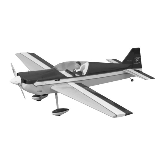
Congratulations and thank you for purchasing the Great ® Cover the Model with MonoKote Film ............39 Planes Giles G-202. We’d like to provide you a bit of history Covering Technique ..................39 on our selection of this aircraft as the newest release in the Suggested Covering Sequence ..............39 Paint the Model....................39... -
Page 3: Precautions
Giles through its paces. When you have a feel for your Giles G-202, the throws can DECISIONS YOU MUST MAKE be increased to high rates (illustrated in the instructions) to really showcase the aerobatic potential. -
Page 4: Building Supplies And Tools
Pilot (DGA 1/4 scale sportsman pilot used in protype, Made of durable, lightweight aluminum, Easy-Touch DGAQ2010) Sanders have a uniquely contoured handle that lets you Fueling system [Great Planes Easy Fueler ™ , (GPMQ4160) work longer with less fatigue! The incredibly flat sanding or Aluminum Fuel Line Plug, (GPMQ4166)] surface removes high spots with ease. -
Page 5: Building Notes
Where you see the term “glue,” it is at your option to select the Clevis installation tool (GPMR8030) thickness of CA with which you are most comfortable. If the Heat gun (TOPR2000) step indicates a particular thickness of glue, be sure to use the Trim Seal Tool ™... -
Page 6: Die-Cut Patterns
DIE-CUT PATTERNS... -
Page 7: Build The Tail Surfaces
You may remove the stabilizer and elevator drawing from the wing plan by cutting along the dashed line. Don’t forget to cover the plan with Great Planes Plan Protector so the glue won’t stick to the plan. 3. Using two 3/16" x 1/2" x 24" balsa sticks, fit and glue the stab leading edges and stab trailing edge. -
Page 8: Build The Fin
1. Remove the stab plan from your building board, and lay out the fuselage plan. Cover the fin area of the plan with Great Planes Plans Protector so the glue won’t stick to the plan. C. Turn the sheet over and place weights on top of the sheet to hold it. -
Page 9: Build The Rudder
8. Using leftover 1/16" balsa sheet, sheet the vertical post with the grain of the balsa running vertically. 9. Repeat steps 6, 7 and 8 to sheet the other side of the fin. 3. From a 3/16" x 1/2" x 24" balsa stick, cut the fin leading edge and fin trailing edge. -
Page 10: Building The Elevator
1. Place the stab over its location on the plan and lightly mark the hinge locations on the trailing edge with a ballpoint pen. Mark the hinge locations on the elevators in the same manner. 2. Using the 1/4" x 5/16" x 24" balsa stick, fit and glue the three rudder ribs. -
Page 11: Finish The Tail Surfaces
We have simplified the task of cutting hinge slots with the Right now, while the building board is clear, is a great time introduction of the Great Planes Slot Machine. This to assemble the wing sheeting. simple electric tool cuts a perfect width slot for use with CA hinges. -
Page 12: Build The Wing Panels
1. Tape the right wing plan to the building board, and cover the wing drawing with Great Planes Plan Protector. Remember, we are building the right wing upside-down over the right wing bottom view. - Page 13 6. Carefully slide the die-cut 3/32" balsa TE web and the die-cut 3/32" balsa LE web over the ribs in their notches until the top of the webs are flush with the top of each rib. Take your time and be gentle; this balsa structure is still fragile at this point, but when finished will provide you a strong, light platform.
-
Page 14: Sheet The Wing Panel Center Section
and the LE web. Working quickly, pull the sheeting forward 16. Measure 2-3/8" in from the cut you just made and as you press it down to the ribs and the LE web. Use cut off the excess sheeting, making a 1/16" x 2-3/8" x 24" weights to hold the sheeting to the ribs and LE web until the trued aileron sheet. - Page 15 4. Position the 6-1/4" long sheet flush with the 8. Set the wing right-side up on the building board. outboard edge of R-3 (next to, but not touching the aileron From a piece of leftover sheeting, make a sheeting end cap), and pressed against the trailing edge of the TE support for the inboard side of the aileron servo tray as sheeting.
-
Page 16: Join The Wing Panels
11. Turn the wing right-side up again, and use a sanding block to shape the LE web so it aligns with the tops 3. Cut the sheeting along the line drawn in step 2 and of the ribs and the shape of the airfoil. along R-2A, and remove the leftover piece of sheeting. -
Page 17: Finish The Top Of The Wing
Finish the Top of the Wing 5. Place the wing with the left wing panel right-side up on top of the wing jig which is pinned to the right wing plan. Pin the left bottom spar to the plans. You are now 1. - Page 18 the tip rib and is aligned with the centerline of the wing. Glue the sheeting to the top of each rib and the LE web as you did with the bottom sheeting. Use weights to hold the sheeting to the ribs and LE web until the CA cures. 12.
-
Page 19: Finish The Ailerons
24. Using the plans as a reference, cut the servo wire holes in the top of the wing. Note: Use a nickel as the template to draw the circles. 4. Glue the 1/8" x 1" x 24" balsa wing trailing edge onto the TE of the right wing panel, leaving excess Finish the Ailerons extending both top and bottom. -
Page 20: Build The Fuselage
3. Assuming you are using the included Great Planes adjustable .60 - 1.20 engine mount, drill the four 7/32" engine mount holes at the punch marks as shown in the 6. -
Page 21: Assemble The Fuselage
7. Referring to the photo, confirm that you have properly 5. Use a square to check that the fuse sides are labeled the fuse sides. Select the right fuse side, and cut off perpendicular to the building board. Double-check to make the tab as shown. -
Page 22: Assemble The Belly Pan
9. When you are satisfied with the fit, use 30-minute epoxy to secure the wing bolt block in place in the fuse doublers and F-4. Assemble the Belly Pan 5. Using the aft belly pan former and belly pan sides as a guide, sand the trailing edge of the belly pan bottom flush as shown in the photo. - Page 23 belly pan as shown in the photo helps minimize excess CA 5. Fit the wing back onto the fuse, drill the second dowel outside of the belly pan which would have to be sanded. hole, remove the wing and epoxy the second dowel in place.
-
Page 24: Finish The Bottom Of The Fuselage
15. Repeat steps 13 and 14 to mount the paper tube over the other wing bolt. Sand the paper tubes flush with the belly pan bottom. 4. Position and glue the die-cut 1/8" ply landing gear plate in place. Note: The landing gear plate glues flat to the landing gear rails. -
Page 25: Install The Pushrod & Antenna Tubes
8. Notice that the leading edge of the landing gear legs are straight, and the trailing edge is tapered. Mark an arrow on the center of the gear pointing toward the straight side (leading edge). 9. Center the landing gear on the fuse and press it tight against the forward fuse bottom. -
Page 26: Installing The Tank Tray & Servo Tray
required for a perfect fit. Sand lightly as needed until the tank tray fits snugly in place with the tank tray retainer, without bowing formers F-2 and F-3. 5. You’re about to mix epoxy to work on the aft end of the fuselage. -
Page 27: Build The Front Fuselage Deck
Build the Front Fuselage Deck 5. From a 1/8" x 1/8" x 24" balsa stick, cut two 6-5/8" long top gluing stringers. Use a straightedge held on top of both the firewall and the instrument panel to position the 1. From the 3/8" x 6" balsa triangle stock, fit and glue the left top gluing stringer. -
Page 28: Mount The Stabilizer To The Fuselage
10. Liberally wet the left front deck sheeting with an ammonia/water mix to help it bend. Gradually wrap the sheeting over the fuse top. Holding it in place, use a hobby knife to carefully trim the sheeting so that it fits against but does not bow the main stringer. -
Page 29: Mount The Fin To The Fuselage
sides and allow the epoxy to dry completely. Note: Be sure 4. Place the stab on the stab base with the center marks no epoxy ran onto the clamps, attaching them to the aligned, then use a large T-pin to attach only the trailing airplane. - Page 30 4. Just as you did for the front deck, select a 1/8" x 1/8" x 24" balsa stick. Cut a left top gluing stringer to fit 9. Position one of the turtle deck sheets on the left from TD-1 to TD-2 against the turtle deck main stringer. side of the fuselage as shown.
-
Page 31: Finish The Cockpit
13. Trim the sheeting, the main and gluing stringers flush with TD-1. Trim the sheeting flush with the trailing edge 1. Cut the “spreader bars” from the supplied Great Planes of the fin. engine mount, then use a hobby knife to remove any flashing leftover from the molding process so that the 14. -
Page 32: Install The Servos & Make The Pushrods
Make adjustments to the bends in the wire so the pushrod aligns with the 5. Use the Great Planes Dead Center ™ Engine Mount carburetor arm on the engine, then temporarily connect the Hole Locator to mark the locations of the bolt holes. - Page 33 behind the servo arm. Slide a solder clevis onto the pushrod at the rudder servo. Attach the clevis to the outer hole on the servo arm and mark the pushrod with a marker at the aft edge of the clevis. Note: Leave the clevis and pushrod installed until after you mount the elevator servos to ensure proper clearance.
-
Page 34: Assemble & Install The Tank
™ works great for this task. Test cap the line with a Great Planes Aluminum Fuel Line Plug fit the tail gear wire in the rudder. Cut a slot in the trailing (not included). This will be the line to fill and drain the edge of the fuse at the marks you made for the nylon tail model. -
Page 35: Assemble The Wheel Pants
3. Test fit the wheel pant halves together and make adjustments where necessary for the best possible fit. 4. Join the wheel pant halves and carefully spot glue them together in just a few places with thin CA. Start by spot gluing the top, then the front and rear where the two halves just butt together. - Page 36 9. Most 2-1/2" wheels (not included) are made to fit 5/32" axles, but the 8-32 screws supplied in this kit for the axles require a larger hole. If the wheel does not roll freely on the 8-32 x 1-1/2" SHCS "axle," enlarge the wheel hub with an 11/64"...
-
Page 37: Assemble The Cowl
6. If the mating strips did not go all the way to the Assemble the Cowl spinner ring, reinforce the unmated areas with fiberglass tape and medium CA. 7. Slide the cowl onto the fuselage. Slide the spinner backplate over the crankshaft and against the drive washer and secure it in place. -
Page 38: Balance The Model Laterally
11. Use a piece of thin cardboard or plastic to make a 1. With the wing level and attached to the model (and template for the cutout in the cowl for the valve cover (if the radio system, engine and muffler installed), suspend necessary), the engine mixture screw and for the glow the model inverted by the propeller shaft and the trailing plug. -
Page 39: Cover The Model With Monokote Film
then blue to match the fuse side, then white, then COVER THE MODEL WITH red stripes) 13. Cockpit (white) MONOKOTE ® FILM 14. Pilot’s Instrument Panel (IP-2) (white) Wing: 1. R-2A ribs (yellow) Covering Technique 2. Wing tips (white, other colors will overlap) 3. -
Page 40: Final Hookups & Checks
FINAL HOOKUPS & CHECKS Attach the Control Surfaces Painting Butyrate Canopies With Top Flite LustreKote ® Top Flite LustreKote is a high quality, fuelproof paint that perfectly matches Top Flite MonoKote. The paint is well suited to putting a high quality finish on ABS but does have a tendency to curl materials such as styrene and butyrate. -
Page 41: Install The Hardware
5. Mount the landing gear to the fuselage with the 8-32 x ASSEMBLE, THEN APPLY 6 DROPS OF THIN CA TO CENTER 3/4" socket head screws and #8 flat washers. OF HINGE, ON BOTH SIDES Final Servo & Receiver Installation 1. -
Page 42: Set The Control Throws
5. Thread the antenna under the servo tray, being 12. Attach the solder-on clevis to the servo arm. Making careful not to entangle it in any of the wiring. Take a cut-off sure the rudder is centered, thread the nylon clevis in or out piece of servo arm with at least two holes in it, and feed the on the pushrod until it can be attached to the control horn antenna through two of the holes, making a strain relief... -
Page 43: Install The Cowl & Canopy
If, after you become 6. Reposition the canopy on the fuselage and confirm comfortable with your Giles G-202, you would like to that it covers the exposed wood. Glue the canopy to the adjust the throws to suit your tastes, that’s fine. Too... -
Page 44: Preflight
After initial trim flights and when you become vibration. Not only may engine mounting screws vibrate more acquainted with your Giles G-202, you may wish to out, possibly with disastrous effect, but vibration may also experiment by shifting the balance up to 1/4" forward or damage the radio receiver and battery. -
Page 45: Find A Safe Place To Fly
Find a Safe Place to Fly Engine Safety Precautions Since you have chosen the Giles G-202 we assume that Note: Failure to follow these safety precautions may you are an experienced modeler. Therefore, you should result in severe injury to yourself and others. -
Page 46: Radio Control
Sloppy fit of clevis pin in horn; Elasticity present in flexible plastic pushrods; Side-play of pushrod in guide tube caused by We recommend that you take it easy with your Giles G-202 tight bends; Sloppy fit of Z-bend in servo arm; Insufficient glue used when gluing in the elevator joiner wire or aileron torque rod;... -
Page 47: Landing
If further information is required, please contact your local hobby dealer, local flying club or call Great Planes at (217) 398-8970. ATV or Travel Volume: ATV is a wonderful feature of A model is not a static object. -
Page 48: Flight Trimming Chart
If so, you need some down thrust, or nose weight. When the thrust is correct, the model should continue along the same Reprinted in part by Great Planes Model Manufacturing Company, flight path for at least a dozen plane lengths before gravity starts to courtesy of Scale R/C Modeler magazine, Pat Potega, Editor, August naturally bring it down. - Page 49 TRIM FEATURE MANEUVERS OBSERVATIONS CORRECTIONS CONTROL Fly general circles and Try for hands off straight Readjust linkages so that CENTERING random maneuvers. and level flight. Tx trims are centered. CONTROL Random maneuvers A. Too sensitive, jerky If A, change linkages to THROWS controls.
- Page 50 Great Planes Ultimate Bipe The Ultimate Bipe is among the most celebrated stunt planes ever. Great Planes captures the essence of this air show legend in a stylish, .40-size sport-scale kit. The wings feature a fully symmetrical airfoil. With plug-in struts and only four fasteners, you can quickly remove and reattach the wings right at the field.
-
Page 51: Flight Log
BUILDING NOTES Kit Purchased Date:________________________ Date Construction Finished: _________________ Where Purchased:_________________________ Finished Weight: __________________________ Date Construction Started: __________________ Date of First Flight: ________________________ FLIGHT LOG... - Page 52 TWO VIEW DRAWING Use copies of this page to plan your trim scheme Printed in USA...
Need help?
Do you have a question about the Giles G-202 and is the answer not in the manual?
Questions and answers