Panasonic KX-TA616 Installation Manual
Advanced hybrid system
Hide thumbs
Also See for KX-TA616:
- Manual de instalación (268 pages) ,
- Installation manual (268 pages) ,
- Operating instructions manual (132 pages)

Related Manuals for Panasonic KX-TA616


Summary of Contents for Panasonic KX-TA616
-
Page 1: Installation Manual
Advanced Hybrid System Installation Manual KX-TA308 KX-TA616 MODEL Please read this manual before connecting the Advanced Hybrid System. This manual was printed with soy based ink. -
Page 2: System Highlights
2– 23 Hybrid Calling from the outside (Direct Inward System Access) This system can accept Panasonic analog proprietary telephones. Also, single line External callers can call extensions in the devices such as single line telephones, system. If you install an optional card,... - Page 3 Precautions • Keep the unit away from heating appliances and electrical noise generating devices such as fluorescent lamps, motors and televisions. These noise sources can interfere with the performance of the Advanced Hybrid System. • This unit should be kept free of dust, moisture, high temperature (more than 40˚C) and vibration, and should not be exposed to direct sunlight.
- Page 4 Precautions For your future reference SERIAL NO. DATE OF PURCHASE (found on the bottom of the unit) NAME OF DEALER DEALER’S ADDRESS Note • This Installation Manual does not show complete model number that indicate the country where your models should be used. The model number of your unit is found on the label affixed to the unit.
-
Page 5: Default Values
Introduction Structure of the Manual This manual consists of the following sections: Section 1. Basic System Construction Provides general information on the system including connection diagrams. Section 2. Installation Contains the system installation and wiring instructions, as well as how to install the optional card. -
Page 6: Table Of Contents
Contents Section 1 Basic System Construction Section 2 Installation Before Installation ................. Unpacking ....................Names and Locations ................Wall Mounting..................Frame Ground Connection ..............Opening the Top Front Cover.............. Outside (CO) Line Connection ............Extension Connection ................External Pager (Paging Equipment) Connection....... 2-10 2.10 External Music Connection.............. - Page 7 Contents Conference (3-Party) ................3-10 Conference (5-Party) ................3-11 Data Line Security................3-11 Date and Time Setting ................ 3-12 Direct In Line (DIL)................3-12 Direct Inward System Access (DISA)..........3-13 Display Contrast Adjustment (KX-T7330/KX-T7030/KX-T7130/KX-T7033 only)...... 3-20 Distinctive Dial Tone................3-20 Do Not Disturb (DND)...............
- Page 8 Contents Paging ....................3-41 Paralleled Telephone Connection ............3-42 Personal Speed Dialing ..............3-42 Pickup Dialing ..................3-43 Polarity Reverse Detection..............3-43 Power Failure Transfer ............... 3-44 Preferred Line Assignment — Incoming ........... 3-44 Preferred Line Assignment — Outgoing..........3-45 Proprietary Telephone setting Data Default Set.........
- Page 9 Contents [007] Time (Day/Night/Lunch) Service Start Time ......[008] Operator Assignment .............. 4-10 [009] Extension Number Assignment ..........4-10 [010] LCD Time Display Selection ..........4-11 [100] Hunting Group Set ..............4-12 [101] Hunting Type ................4-12 [102] Voice Mail Port ..............4-13 [103] DTMF Integration ..............
- Page 10 Contents [301] Toll Restriction — System Speed Dialing Boundary Class .. 4-30 [302]–[305] Toll Restriction — Classes 2 through 5 Denied Codes .. 4-31 [306] Toll Restriction — Exception Codes ........4-32 [309] Emergency Dial Number Set ..........4-32 [310] Account Codes ............... 4-33 [311] Automatic Pause Insertion Codes ..........
- Page 11 Contents [519] DISA OGM Mute Time ............4-58 [520] UCD Group ................4-59 [521] UCD Busy Waiting Time ............4-59 [522] UCD OGM Message Interval Time ........4-59 [523] UCD Busy Mode ..............4-60 [524] UCD Intercept Mode .............. 4-60 [525] UCD Ringing Time before Intercept ........
- Page 12 Contents Section 5 Appendix Default Values ..................Specifications ..................Section 6 Troubleshooting While Installing ..................While Connecting .................. While Operating ..................Section 7 Programming Tables Template...
-
Page 13: Basic System Construction
Section 1 Basic System Construction... -
Page 14: System Connection Diagram
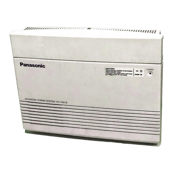
The KX-TA308 has a basic capacity of 8 extensions and 3 outside (CO) lines, and the KX- TA616 has 16 extensions and 6 outside (CO) lines. It is capable of supporting Panasonic analog proprietary telephones, and single line devices such as single line telephones, facsimiles and data terminals. - Page 15 Basic System Construction KX-TA616 6 Outside (CO) Lines to outside lines 1 – 6 (Lightning Protectors) car batteries External Music Source Amplifier Speaker Printer Computer Extension jacks 01 – 16 (initial) 24 Extensions Extension jacks 17 – 24 (additional) (two pair)
- Page 16 Basic System Construction...
- Page 17 Section 2 Installation...
-
Page 18: Before Installation
(It is preferable not to install the system in the same room with the above equipment.) 7. Install at least 1.8 m away from radios and televisions. (Both the system and Panasonic proprietary telephones) 8. Do not obstruct area around the system (for reasons of maintenance and inspection — be especially careful to allow space for cooling above and at the sides of the system). -
Page 19: While Installing
4. Please use one pair telephone wire for extension connection of (telephone) equipment such as single line telephones, data terminals, answering machines, computers, voice processing systems, etc., except Panasonic proprietary telephones (e.g. KX-T7330). 5. Unplug the system during wiring. After all of the wiring is completed, plug in the system. -
Page 20: Unpacking
Outside (CO) Line Modular Jacks Serial Interface Power Switch Connector (RS-232C) Side View Battery Interface Protective Earth Terminal Power Indicator AC Inlet KX-TA616 External Music Jack Paging Jack Extension Modular Jacks Strap Hole Outside (CO) Line Modular Jacks Serial Interface Power Switch Connector (RS-232C) -
Page 21: Wall Mounting
Wall Mounting This set is designed for wall mounting only. The wall where the main unit is to be mounted must be able to support the weight of the main unit. If screws other than the ones supplied are used, use screws with the same diameter as the ones enclosed. Mounting on a Wooden Wall Mounting on a Concrete or Mortar Wall... -
Page 22: Frame Ground Connection
Frame Ground Connection IMPORTANT!!! Connect the frame of the main unit to the ground. 1. Loosen the screw. 2. Insert the grounding wire (user- supplied). 3. Tighten the screw. To the ground Screw 4. Connect the grounding wire to the ground. - Page 23 Outside (CO) Line Connection Connection 1. Insert the modular plugs of the telephone line cords (2-conductor wiring) into the modular jacks (CO 1 through 3) on the system. 2. Connect the line cords to the terminal board or the modular jacks from the Central Office. View of TEL Jack (Outside (CO) Line) T: Tip R: Ring...
-
Page 24: Outside (Co) Line Connection
Outside (CO) Line Connection Installation Lightning System Protectors Terminal EXTN Board Protective Earth Terminal EXTN EXTN Frame Ground Outside line Ground EXTN: Extension line TEL: Telephone Installation of an Earth Rod Lightning Protectors Grounding Wire System (Underground) 1) Installation location of the earth rod ..Near the protector 2) Check obstructions . -
Page 25: Extension Connection
Extension Connection Extension jacks 01 through 08 for the KX-TA308 and extension jacks 01 through 16 for the KX-TA616 can be used for all kinds of telephones. Telephone Wiring The maximum length of the extension line cord (twisted cable) which connects the system and the extension is as follows. -
Page 26: External Pager (Paging Equipment) Connection
External Pager (Paging Equipment) Connection One external pager (user-supplied) can be connected to the system as illustrated below. Use an EIAJ RC-6701 A plug (2-conductor, ø 3.5 mm in diameter). • Output impedance: 600 Ω Maximum length of the cable AWG 18 –... -
Page 27: External Music Connection
2.10 External Music Connection One music source, such as a radio (user-supplied), can be connected to the system as illustrated below. Insert the plug to the earphone/headphone jack on the external music source. Use an EIAJ RC-6701 A plug (2-conductor, ø 3.5mm in diameter). •... -
Page 28: [610] Paralleled Telephone Connection
Any single line telephone can be connected in parallel with a proprietary telephone as follows. Using a Modular T-Adaptor Modular T-Adaptor (Panasonic KX-J66 or USOC RJA2X) 2-conductor wiring cord Connect pins “T” and “R”. 4-conductor wiring cord For a proprietary telephone: Connect pins “T”, “R”, “H”... -
Page 29: Polarity Sensitive Telephone Connection
2.12 Polarity Sensitive Telephone Connection If your telephone is polarity sensitive, follow the procedure below: 1. Complete all the required extension wiring. 2. Confirm that dialing can be done from all the extensions using a touch-tone telephone. If dialing fails, the polarity between the extension and the system must be reversed. -
Page 30: Printer And Pc Connection
2.13 Printer and PC Connection A user-supplied printer or personal computer (PC) can be connected to the system. These are used to print out or refer to the SMDR call records and system programming data. Connect the printer cable or the PC cable to the Serial Interface (RS-232C) connector. The cable must be shielded and the maximum length is 2 m. - Page 31 2.13 Printer and PC Connection Connection Chart for a Printer / Personal Computer with the System If you connect a printer or a PC with a 9-pin cable, follow the chart below. System 9-pin Cable Printer/PC Circuit Circuit Signal Signal type type name...
- Page 32 2.13 Printer and PC Connection Serial Interface (RS-232C) Signals Frame Ground: FG Connects the unit frame and the earth ground conductor of the AC power cord. Transmitted Data: SD (TXD) ..... . (output) Conveys signals from the unit to the printer.
-
Page 33: Location Of Optional Cards
2.14 Location of Optional Cards The location of the optional cards is shown below. Precaution To protect the printed circuit boards (P-boards) from static electricity, do not touch parts on the P-boards in the main unit and on the optional cards. If accessing the parts is required, wear a grounding strap. - Page 34 2.15 OGM/FAX Detection Card Installation 2. Open the bottom front cover. Bottom front cover 3. Attach the OGM/FAX Detection card. OGM/FAX Detection Card (KX-TA30891) Note Please do not damage this part. 4. Insert the flat cables to the card connector. Flat cables 5.
-
Page 35: Doorphone And Door Opener Connection
2.16 Doorphone and Door Opener Connection Four doorphones (KX-T30865) and 4 door openers (user-supplied) can be installed. Maximum cable length The maximum length of the doorphone and door opener line cord which connects the system is as follows. Diameter of the line Max. - Page 36 2.16 Doorphone and Door Opener Connection Doorphone/Door Opener Installation Attach the optional Doorphone/Door Opener Card to the main unit, connect the cord to the Doorphone/Door Opener Card Connector and secure the screw. Doorphone Connectors Screw Door Opener Terminal Doorphone/Door Opener Card (KX-TA30860) Doorphone/Door Opener Card Card Connector...
- Page 37 2.16 Doorphone and Door Opener Connection Wiring of the Doorphone 1. Connect the Doorphone/Door Opener Card to the terminal boxes using 4-conductor modular connectors. 2. Connect the wires of doorphones 1 and 3 to the red and green screws on the terminal box. 3.
- Page 38 2.16 Doorphone and Door Opener Connection Connecting Door Openers 1. While pressing the button below a hole with a driver, insert the wire from the door opener into the hole. Door opener 1 Door opener 4 Door opener 2 Door opener 3 To the door openers 2.
-
Page 39: Backup Batteries Connection
2.17 Backup Batteries Connection Two car batteries can be connected to the system as a backup power supply in the event of a power failure. 1. Attach the cables (KX-A227) and user-supplied 2 car batteries (12 VDC each) as shown below. -
Page 40: Installing A 3-Co Line & 8 Ext Expansion Card (Kx-Ta30877)
2.18 Installing a 3-CO Line & 8 Ext Expansion Card (KX-TA30877) and 8 SLT Extn. Expansion Card (KX-TA30874) 3-CO Line and 8 Ext Expansion Card Installation (KX-TA30877) — for KX-TA308 only To add 3 outside (CO) lines (outside (CO) lines 4 through 6) and 8 extensions (extension jacks 09 through 16), use an optional 3-CO Line and 8 Ext Expansion Card (KX-TA30877). - Page 41 2.18 Installing a 3-CO Line & 8 Ext Expansion Card (KX-TA30877) and 8 SLT Extn. Expansion Card (KX-TA30874) 3. After cutting the areas, be sure to cut off any excess plastic in order to make the surface smooth. 4. First, insert the plastic spacer into the hole on the KX-TA30877. Attach the 2 extension connectors to the system, install the KX-TA30877 and secure the 2 extension bolts.
- Page 42 2. If your system is a KX-TA308, remove the lower front panel in the same way as installing a KX-TA30877. If you install the KX-TA30874 to a KX-TA616 or a KX-TA30877, which is connected to a KX-TA308, remove the top front panel with pliers.
- Page 43 2.18 Installing a 3-CO Line & 8 Ext Expansion Card (KX-TA30877) and 8 SLT Extn. Expansion Card (KX-TA30874) 4. Attach the 2 extension connectors to the system first, install the KX-TA30874 and secure the 2 screws. Screws 8 SLT Extension Expansion Card (KX-TA30874) Extension Connectors 5.
- Page 44 2.18 Installing a 3-CO Line & 8 Ext Expansion Card (KX-TA30877) and 8 SLT Extn. Expansion Card (KX-TA30874) Installing the KX-TA30877 and KX-T30874 — for KX-TA308 only 1. Install the KX-TA30877 first and then the KX-TA30874. Screws 8 SLT Extension Expansion Card (KX-TA30874) Extension Bolts Extension Connectors...
-
Page 45: Auxiliary Connection For Power Failure Transfer
2.19 Auxiliary Connection for Power Failure Transfer Power failure transfer connects a specific single line telephone (SLT) to selected outside (CO) lines in the event of system power failure, as follows. Outside (CO) line 1 – extension (T, R) jack 01 Outside (CO) line 4 –... -
Page 46: Securing The Cords
2.20 Securing the Cords 3. Wrap the strap around all of the cords. 4. To remove the rivet, use a screw driver as shown below. 2.21 Closing the Front Cover 1. Replace the covers and tighten the screws. 2. Tie together all of the connected cords and attach them to the wall so that the cords cannot be pulled out of the system. -
Page 47: Starting The System For The First Time
2.22 Starting the System for the First Time 1. Set the Power Switch to the “OFF” position. 2. Plug the AC power cord into the system and an AC outlet. 3. Turn the Power Switch on. (The power indicator will light.) 4. - Page 48 2.22 Starting the System for the First Time Plug Adaptor The plug adaptor (included) is to be used if the power plug will not fit your socket. Assemble as shown below, using the plug which fits your socket. In this case, be sure to connect the frame of the main unit to ground because the ground line in the power cable cannot be used.
-
Page 49: System Restart
2.23 System Restart After starting the system, if the system does not operate properly, restart the system. Before restarting the system, try the system feature again to confirm whether there definitely is a problem or not. System Restart causes the following. •... -
Page 50: System Data Clear
2.24 System Data Clear When the system does not operate properly after restarting, you can clear the programming data stored in the system. The system will restart with the default settings. First, try system program [999] “System Data Clear” by following step 4 in 2.22, “Starting the System for the First Time”. -
Page 51: Features A
Section 3 Features... -
Page 52: Absent Message Capability
Features Absent Message Capability Allows an extension user to set a message which will be displayed at the calling extension to show the reason for the called extension’s absence. One of 6 messages can be programmed as desired, which are available for any telephone (single line telephone or proprietary telephone). -
Page 53: Alternate Calling - Ring/Voice (Voice To Ring Only)
Features • Required System Programming [310] Account Codes [605] Account Code Entry Mode [805] SMDR Account Code Selection • Related Feature References Station Message Detail Recording (SMDR), Toll Restriction Override by Extension Password • Operating Instructions Reference 1.7 Useful Features, “Calling with Account Codes (Account Code Entry)” Alternate Calling –... -
Page 54: Automatic Outside (Co) Line Access Number
Features Automatic Outside (CO) Line Access Number An Automatic Line Access number (0 or 9) can be programmed. When an extension user dials an Automatic Line Access number before a telephone number, an available outside (CO) line from the assigned lines in program [419] is seized automatically. If “0” is selected in program [121], the operator call will be “9”... -
Page 55: Call Forwarding
Features Call Forwarding Allows an extension user to transfer incoming calls automatically to another extension or to an external destination. The following types are available. All Calls: All incoming calls are forwarded to another extension. Busy or No Answer: All incoming calls are forwarded to another extension when the extension user does not answer within the programmed time in [202] or when the extension is busy. -
Page 56: Call Park
Features Call Park Allows an extension user to place a held call into a system parking area. Any extension user can retrieve the parked call to perform other operations. Up to 10 calls can be parked at the same time. •... -
Page 57: Call Pickup
Features Call Pickup <Directed Call Pickup> Allows an extension user to answer a call ringing at any other extension. <Group Call Pickup> Allows an extension user to answer a call ringing at another extension, if the call is ringing within the user’s extension group assigned in program [600]. <Call Pickup Deny>... -
Page 58: Call Transfer - To Extension
Features Call Transfer – to Extension Allows an extension user to transfer a received call, an intercom or an outside call, to another extension. Two types are available. Screened Call Transfer: Announces the call to another extension before completing the transfer. Unscreened Call Transfer:Immediately releases the call to another extension without an announcement. -
Page 59: Call Waiting
Features • To join the conversation again after transferring the call, press the corresponding CO button. A conference call will be established. This feature is not available for a single line telephone. • Required System Programming [111] Hold Music Selection [205] Outside-to-Outside (CO-to-CO) Line Duration Time Limit [606] Call Transfer to an Outside (CO) Line •... -
Page 60: Conference (3-Party)
Features Conference (3-party) <Conference> During a 2-party conversation, an extension user can add a third party to make a 3-party conference. The maximum number of members of a conference can be programmed in program [116]. <Conference, Unattended> When a proprietary telephone user is in a 3-party conference with 2 external parties, the user can leave the conference to allow the other 2 parties to continue the conversation. -
Page 61: Conference (5-Party)
Features Conference (5-party) Allows an extension user to establish a 5-party conference when “5 party C-2 E-5” is selected in program [116]. • Up to 2 external parties can participate in a conference call. • All 5 parties can be extensions. •... -
Page 62: Date And Time Setting
Features Date and Time Setting A manager or operator can adjust the current time. • Required System Programming [000] Date and Time Setting • Operating Instructions Reference 1.8 Operator / Manager Service Features, “Date and Time Setting” Direct In Line (DIL) Enables an incoming outside call to go directly to a specified extension. -
Page 63: Direct Inward System Access (Disa)
Features Direct Inward System Access (DISA) Allows an outside caller to access specific system features as if the caller is an extension in the system. The caller can have direct access to features such as: • Placing an incoming call to an extension, extension group or operator. The caller also has the option of dialing the route for an extension using a 1 digit number (DISA built- in auto attendant number) via DISA calls. - Page 64 Features • The duration of outside-to-outside (CO-to-CO) line calls can be limited in program [205]. When the specified time expires, both lines are disconnected. A warning tone is sent to both parties 15 seconds before the time-limit. • To detect the end of an outside-to-outside (CO-to-CO) line call, CPC Signal Detection can be assigned.
- Page 65 Features DISA Operation Calling an extension by following the outgoing message from an External Party In None Security Mode DISA phone no. extension no. Enter the DISA phone number. Ringback tone and Enter the extension number. Ring back tone DISA outgoing message •...
- Page 66 Features Calling an external party by following the outgoing message from an External Party In None Security Mode DISA phone no. line acccess code phone no. Enter the DISA phone number. Ringback tone and Dial tone Enter the phone number Enter a DISA outgoing message of the external party.
- Page 67 Features Flow chart of possible cases and results for DISA calls An outside line call is made. The caller reaches the DISA line. With optional Without optional OGM/FAX Detection Card OGM/FAX Detection Card (Internal DISA) @ @ @ @ @ @ @ @ e ? @ @ @ @ @ @ @ @ e ? @ @ @ @ @ @ @ @ ? e @ @ @ @ @ @ @ @ e ? @ @ @ @ @ @ @ @ ? e @ @ @ @ @ @ @ @ e ? @ @ @ @ @ @ @ @ ? e @ @ @ @ @ @ @ @ e ? @ @ @ @ @ @ @ @ ? e @ @ @ @ @ @ @ @ e ? @ @ @ @ @ @ @ @ ? e @ @ @ @ @ @ @ @ e ? @ @ @ @ @ @ @ @ ? e @ @ @ @ @ @ @ @ e ? @ @ @ @ @ @ @ @ ? e @ @ @ @ @ @ @ @ e ? @ @ @ @ @ @ @ @ ? e @ @ @ @ @ @ @ @ e ? @ @ @ @ @ @ @ @ ? e @ @ @ @ @ @ @ @ e ? @ @ @ @ @ @ @ @ ? e @ @ @ @ @ @ @ @ e ? @ @ @ @ @ @ @ @ ? e @ @ @ @ @ @ @ @ e ? @ @ @ @ @ @ @ @ ? e @ @ @ @ @ @ @ @ @ @ @ @ @ @ @ @ e ?
- Page 68 Features *1: The DISA Delayed timer starts. This is the time between a call reaching the system and being received. The time is assigned in program [504]. *2: When the assigned time period in program [519] expires, the system sends a short beep to the caller.
- Page 69 Features *10: The DISA Busy Mode is selected in program [506]. There are 3 modes as follows. • Disconnect – the caller hears a busy tone and a call is disconnected. • Call Waiting – the destination extension hears a call waiting tone if they have enabled Call Waiting.
-
Page 70: Display Contrast Adjustment
Features Display Contrast Adjustment (KX-T7330/KX-T7030/KX-T7130/KX-T7033 only) Allows a display proprietary telephone user to adjust the display contrast with the CONTRAST selector. • Operating Instructions Reference 1.2 Proprietary Telephone Settings, “Display Contrast Adjustment” Distinctive Dial Tones An extension user will hear 3 types of dial tone patterns which give information about the features activated on the telephone. -
Page 71: Do Not Disturb (Dnd)
Features Do Not Disturb (DND) <Do Not Disturb (DND)> Allows an extension user to prevent other parties from disturbing them. The extension will not receive intercom or outside calls. <Do Not Disturb (DND) Override> Allows an extension user enabled in program [609] to call an extension which has set the Do Not Disturb (DND) feature. -
Page 72: Doorphone Call
Features • Connection Reference 2.16 Doorphone and Door Opener Connection • Required System Programming [703]–[705] Door Opener Assignment — Day/Night/Lunch [709] Door Opener Time • Related Feature Reference Doorphone Call • Operating Instructions Reference 1.7 Useful Features, “Door Opener” Doorphone Call Up to 4 Doorphones (KX-T30865) can be installed. -
Page 73: Dss Console
Features DSS Console The Direct Station Selection (DSS) Console provides direct access to extensions, a busy lamp display, as well as 16 PF (Programmable Feature) buttons. The DSS Console must be programmed to work with a proprietary telephone (PT). The jack number of the DSS Console and its associated PT are assigned in programs [003] and [004]. -
Page 74: Executive Busy Override
Features Executive Busy Override <Executive Busy Override – Extension> Allows an extension user enabled in program [608] to interrupt an existing intercom call. A 3-party conference will be established. <Executive Busy Override – Outside (CO) Line> Allows a proprietary telephone user enabled in program [608] to interrupt an existing outside call or add a third party. -
Page 75: Extension Group
Features Extension Group The system supports 8 extension groups. In an extension group, the following features can be activated. • Group Call Pickup: Any member of an extension group can pick up a call directed to another member in the same group. •... -
Page 76: External Feature Access
Features External Feature Access Allows an extension user to access special features (e.g. Call Waiting) offered by the Central Office or host PBX. This is done by placing the current call on hold and sending a flash signal using either the FLASH button or the feature number. This feature is effective only during an outside call. -
Page 77: Flexible Buttons
Features Flexible Buttons A proprietary telephone (PT) user can change the flexible buttons on the telephone and DSS console to certain function buttons. For example, if the telephone has more CO buttons than available outside (CO) lines, the unused CO buttons may be changed to One-Touch Dialing buttons, etc. -
Page 78: H Handset/Headset Selection
Features Handset/Headset Selection (KX-T7330/KX-T7030/KX-T7130/KX-T7033 only) The system supports the use of headsets with proprietary telephones. Switch the selection mode before using the headset (optional). • Operating Instructions Reference 1.2 Proprietary Telephone Settings, “When Using the Headset” Handsfree Answerback Allows a proprietary telephone with a speakerphone to answer an intercom call without lifting the handset. -
Page 79: Hold
Features Hold <Call Hold> Allows an extension user to place an intercom and/or outside call. The held call can be retrieved by the user who held it, or by any other extension (Call Hold Retrieve). With a single line telephone (SLT), either one outside or intercom call can be held at one time. -
Page 80: Hookswitch Flash
Features Hookswitch Flash Flashing the hookswitch is used to allow a single line telephone user to hold a call for transferring or holding, if the flash time is within the assigned time in program [207]. The procedure to transfer a call or hold is determined in program [104] “Hold Mode Selection”. Flashing the hookswitch can be also used to disconnect a call, if the flash time is more than the assigned time in program [207]. -
Page 81: Intercept Routing
Features Intercept Routing Provides automatic redirection of incoming outside calls via the DISA or UCD feature. The Intercept Routing feature works in the following 2 cases. 1) When nothing is dialed after a dial tone or OGM is sent to the caller. (The DISA feature only) 2) When the call is not answered within a programmed time. -
Page 82: Language Selection
Features Language Selection The selected language in program [615] is shown on the LCD display of a proprietary telephone during operation and Proprietary Telephone Settings, but not used during System Programming. • Required System Programming [615] LCD Language Assignment Limited Call Duration The system disconnects 2 types of outside outgoing calls when a specific timer expires. -
Page 83: Line Access Buttons
Features Line Access Buttons A proprietary telephone (PT) user must assign one of the following 3 types of CO buttons to flexible CO buttons in the Proprietary Telephone Settings. This allows making or receiving outside calls. The default setting for the flexible CO buttons (CO 1 – CO 6) are Single-CO (S-CO) buttons. -
Page 84: Log-In/Log-Out
Features Log-In/Log-Out Allows an extension user to join (Log-In) or leave (Log-Out) a hunting, DISA ring or UCD group temporarily. Extensions in the log-out mode will not receive calls by Station Hunting, DISA or UCD but will receive other calls, not like the Do Not Disturb (DND) feature. The Log-In/Log-Out button can be assigned to a flexible button in the Proprietary Telephone Settings. -
Page 85: Microphone Mute
Features Microphone Mute Allows a proprietary telephone user to turn off the microphone for privacy. • The user’s voice will only be muted during a handsfree conversation. The user can hear the other party’s voice during Microphone Mute. • Operating Instructions Reference 1.5 During a Conversation, “Turning off the Microphone (Microphone Mute)”... -
Page 86: Operator / Manager Extension
Features • Operating Instructions References 1.2 Proprietary Telephone Settings, “Customizing the Buttons on Your Telephone” One-Touch Dialing button 1.3 Making Calls, “Dialing by Simply Pressing a Button (One-Touch Dialing)” 1.9 DSS Console Features, “Initial Settings” 1.9 DSS Console Features, “One-Touch Dialing” 1.9 DSS Console Features, “One-Touch Access for System Features”... -
Page 87: Outgoing Message (Ogm)
Features Outgoing Message (OGM) Allows the extension assigned as an operator or manager to record up to 2 outgoing voice messages (maximum 30 seconds each). This message is played when a caller accesses the DISA or UCD feature. An optional OGM/FAX Detection Card is required to program the OGM. - Page 88 Features OGM1: “This is A company. For the sales division, press 1. For the service division, press 2. To call the operator, press 0.” OGM2: “This is B company. To contact Mr. A, press 101. To contact Mr. B, press 102.”...
- Page 89 Features Case 7: Uses the DISA or UCD feature for outside (CO) lines – OGM for DISA and UCD. System (DISA) DISA with OGM1 Outside Call To the designated destination (UCD) UCD with The line is busy. (When the line is free.) Outside Call To the UCD group OGM2...
-
Page 90: Outside Calling
Features Outside Calling Allows an extension user to make a call to an external party by using one of the following line access methods. <Automatic Line Access> Allows an extension user to select an available outside (CO) line automatically from the assigned lines in program [419] by pressing the Automatic Line Access number (0 or 9). -
Page 91: Outside (Co) Line Ringing Selection
Features Outside (CO) Line Ringing Selection When an outside call is received at an extension, the user can select whether their extension will ring or not. • Select “Enable” in programs [408]–[410]. • Required System Programming [408]–[410] “Flexible Ringing Assignment — Day/Night/Lunch •... -
Page 92: Personal Speed Dialing
Features Paralleled Telephone Connection Any analog proprietary telephone can be connected in parallel with a single line device, such as a single line telephone, facsimile and data terminal. • System Programming is required. • Connection Reference 2.11 Paralleled Telephone Connection •... -
Page 93: Pickup Dialing
Features Pickup Dialing Allows a single line telephone user to make an outgoing call by going off-hook, if the user has stored the telephone number (up to 32 digits) beforehand. This feature is also known as Hot Line. • A rotary telephone cannot program this feature. •... -
Page 94: Power Failure Transfer
Features Power Failure Transfer During a power failure, specific extension telephones are automatically connected to specific outside (CO) lines. This provides outside (CO) line conversations between the following extensions and outside (CO) lines. Outside (CO) line 1 : extension jack 01 Outside (CO) line 4 : extension jack 09 A single line telephone (SLT) can work in case of a power failure. -
Page 95: Preferred Line Assignment - Outgoing
Features Preferred Line Assignment — Outgoing A proprietary telephone user can select a desired outgoing line preference to make outside calls from the following 3 line preferences. System Programming and Proprietary Telephone Settings are required. Idle Line Preference: When the user goes off-hook, they are connected to an idle line. An idle line is automatically selected from the pre-assigned lines in program [419]. -
Page 96: Pulse To Tone Conversion
Features Pulse to Tone Conversion Allows an extension user to change the dialing mode from Pulse to Tone after entering a telephone number to access services, such as computer telephone services or Voice Mail, which require tones. • This feature only works for outside (CO) lines which have set “Pulse Mode” or ”Call Blocking Mode”... -
Page 97: Ringing Pattern Selection
Features <Saved Number Redial> Allows a proprietary telephone user to save the current external telephone number in the SAVE button during a conversation, so that the extension user can redial the same party later using a simple operation. The saved number can be redialed until another number is stored. A flexible button can be assigned as the SAVE button in the Proprietary Telephone Settings. -
Page 98: Room Monitor
Features Room Monitor Allows a proprietary telephone user to monitor a room or the front door through another proprietary telephone or doorphone without them knowing. The access tone will not be sent to the monitored proprietary telephone and doorphone when monitoring starts. •... -
Page 99: Self-Extension Number Confirmation (Kx-T7330/Kx-T7030/Kx-T7130/Kx-T7033 Only)
Features Self-Extension Number Confirmation (KX-T7330/KX-T7030/KX-T7130/KX-T7033 only) Allows a display proprietary telephone user to confirm their jack and extension number using a simple operation. • Operating Instructions Reference 1.7 Useful Features, “Self-Extension Number Confirmation (KX-T7330/KX-T7030/KX-T7130/KX-T7033 only)” Station Feature Clear Allows an extension user to reset the following station features to the default settings. •... -
Page 100: Station Hunting
Features Station Hunting If a called extension is busy, Station Hunting redirects the incoming call to an idle extension in an extension group in numerical order. Idle extensions are automatically hunted according to programming. The following 2 hunting types are available. Circular hunting: The extensions are hunted one time in numerical order. -
Page 101: Station Lock
Features Station Lock <Electronic Station Lockout> Allows an extension user to lock their station so that other users cannot make outside calls until it is unlocked. Any 4-digit code can be used to lock and unlock an extension. <Electronic Station Lockout – CANCEL ALL> The operator and manager can cancel Electronic Station Lockout of all extensions at one time. -
Page 102: Station Message Detail Recording (Smdr)
Features Station Message Detail Recording (SMDR) Station Message Detail Recording (SMDR) automatically prints out detailed call information of outside calls. A printer connected to the Serial Interface (RS-232C) port can be used to print incoming and outgoing outside calls, as well as print a hard copy of System Programming. -
Page 103: System Data Default Set
Features UCD waiting call: Shows <UCD waiting> for an incoming call via the UCD feature. When the “UCD waiting call” is answered, it becomes a “Received call” and a new record is started. (6) Duration : shows the duration of the call or the UCD call waiting time in Hours/Minutes/Seconds. -
Page 104: System Speed Dialing
Features System Speed Dialing The system supports 100 System Speed Dial numbers (up to 32 digits) assigned in program [001] that are available to all extension users. A System Speed Dial number is dialed out using a simple operation. • Toll Restriction for System Speed Dialing can be assigned by program [301]. •... -
Page 105: Time (Day/Night/Lunch) Service
Features Time (Day/Night/Lunch) Service The system supports the day, night and lunch operation modes. The system operation for making and receiving calls can be different for the day, night and lunch modes. The system operation for toll restriction can be arranged to prevent unauthorized toll calls for each mode. -
Page 106: Toll Restriction
Features Toll Restriction Toll Restriction is a system programmable feature that can prohibit certain extension users from making unauthorized toll calls. Every extension is programmed to belong to one of 5 classes of service (COS). Each COS is programmed to have a toll restriction class for day mode, night mode and lunch mode. There are 5 toll restriction COS numbers available. - Page 107 Features Combination of denied codes and exception codes COS No. Denied Calls Excepted Calls No restriction. No restriction. 20 denied codes programmed in [302]. 20 exception codes (code numbers 01-20) programmed in [306]. 20 denied codes programmed in [302] plus 15 exception codes (code numbers 01-15) 20 denied codes programmed in [303].
-
Page 108: Toll Restriction For System Speed Dialing
Features Toll Restriction for System Speed Dialing Calls originated by System Speed Dialing are restricted depending on the combination of the System Speed Dialing Boundary Class assigned in program [301] and the class of service (COS) assigned to each extension as follows. System Speed Dialing Boundary Class... -
Page 109: Toll Restriction Override By Extension Password
Features Toll Restriction Override by Extension Password Allows an extension user to override toll restriction temporarily to make a toll call from another toll-restricted extension. The user can carry out this feature by entering their extension password, instead of an account code, before dialing the telephone number. The user can make a toll call with their COS number. -
Page 110: Toll Restriction - Station Lock Boundary Class
Features Toll Restriction — Station Lock Boundary Class Allows assigning a toll restriction class for extensions where the Electronic Station Lockout or Remote Station Lock feature has been set. An extension user usually cannot make an outside call at a locked extension, however if a toll restriction class is assigned in program [312], the user can make an outside call at the locked extension. - Page 111 Features [521] UCD Busy Waiting Time [522] UCD OGM Message Interval Time [523] UCD Busy Mode [524] UCD Intercept Mode [525] UCD Ringing Time before Intercept [526] UCD Ringing Time after Intercept [600] Extension Group Assignment • Related Feature References Call Forwarding, Do Not Disturb (DND), Extension Group, Log-In/Log-Out Outline of a UCD (1) When a number of calls have arrived...
- Page 112 Features Flow chart of possible cases and results for UCD calls An outside line call is made. The caller reaches the UCD group. Busy Call Is Intercept Routing employed? Music on Hold is heard. Busy Call The call is sent to Disconnect.
- Page 113 Features *1: An OGM is sent to the caller. When the system detects a cyclic tone or CPC signal while the OGM is being sent, the call is disconnected. *2: Music on hold is selected in program [111] as follows. •...
-
Page 114: Voice Mail Integration
Features Voice Mail Integration This system supports Voice Processing System (VPS) equipment by sending DTMF tones described in program [103]. The DTMF tones sent to a VPS indicate the state of a call (busy, answered, ringing, disconnected, etc.). The DTMF tones also inform a VPS of the destination of a call transferred to the VPS by the Call Forwarding or DISA Intercept Routing –... - Page 115 If the VPS receives a message, the VPS can turn on the MESSAGE button indicator on the corresponding proprietary telephone to notify to the user. (Panasonic KX-TVP series can do this.) The VPS notifies the extension user that there is a message waiting in their mailbox.
- Page 116 • The Voice Mail extension should set Data Line Security to achieve proper recording. • If your VPS is a Panasonic KX-TVP series and KX-TA308 or KX-TA616 cannot be selected in the PBX type setup menu, select “KX-T1232”. Follow the steps for a KX-T1232.
-
Page 117: Volume Control
Features Volume Control Allows a proprietary telephone user to adjust the following volumes, as necessary, by adjusting the corresponding levers or pressing the corresponding buttons. • Handset receiver volume • Headset volume • Ringer volume • Speaker volume • Operating Instructions Reference 1.2 Proprietary Telephone Settings, “Volume Control —... - Page 118 3-68 Features...
-
Page 119: System Programming
Section 4 System Programming... - Page 120 Before System Programming NOTE: System data clear should be performed before System Programming. 2.22, Starting the System for the First Time) Default Setting This system has factory default settings ( 5.1, Default Values). If any of the programming needs to be changed, you can change the setting by System Programming. Default shows you the factory default setting.
-
Page 121: Before System Programming
Before System Programming , – SECRET CLEAR PAUSE STORE AUTO SELECT PREV FLASH NEXT KX-T7130 To enter the programming mode MEMORY PROGRAM system password PROGRAM Press the PROGRAM Set to “PROGRAM” on Press Enter the system password. button. the back of the telephone. (default : 1234) •... -
Page 122: Programming Example
Before System Programming Programming example The following programming instructions assume that you have already entered the programming mode. Example: Program [404] “Outside (CO) Line Group Assignment” Program address Program title [404] Outside (CO) Line Group Assignment Program Assigns a maximum 6 outside (CO) line groups. Each outside (CO) line must be assigned to description an outside (CO) line group. -
Page 123: System Programming
System Programming [000]-[001] [000] Date and Time Setting Sets the current date and time. year NEXT SELECT (00···99) (Jan.···Dec.) (1···31) hour minute SELECT SELECT STORE (Sun···Sat) (1···12) (00···59) (AM/PM) Default ’98 Jan. 1 Thu 12:00 AM • To return to the previous programming step, press •... -
Page 124: [002] System Password
[001]-[002] System Programming • Up to 32 digits, consisting of “0 through 9”, “ ,”, “#”, “PAUSE”, “—”,“FLASH” and “ICM (Secret)”can be stored. • If you are storing an account code assigned in [310] “Account Codes”, enter and the account code after a line access number. •... -
Page 125: [003] Dss Console Port Assignment
System Programming [003]-[004] [003] DSS Console Port Assignment Assigns a maximum of 2 jack numbers to connect the DSS console(s). DSS console no. extension jack no. NEXT STORE (1···2) (02···16) To continue PREV NEXT Default All DSS consoles – Disable (Not stored) •... -
Page 126: [005] One-Touch Transfer Using A Dss Button
[005]-[006] System Programming [005] One-Touch Transfer Using a DSS Button Selects how an outside call is transferred to any extension using the DSS button. With Transfer: Press the DSS button to transfer an outside call. Without Transfer: Press the TRANSFER button then the DSS button to transfer an outside call. NEXT SELECT STORE... -
Page 127: Time (Day/Night/Lunch) Service Start Time
System Programming [007] [007] Time (Day/Night/Lunch) Service Start Time Sets the starting time on a week day basis, when “Automatic” is selected in program [006] “Time (Day/Night/Lunch) Service Changing Mode”. PREV NEXT NEXT SELECT (Every day) (Day/Night/ (Sun···Sat) Lunch-S/Lunch-E) To go to another day of the week To go to another mode minute STORE... -
Page 128: Operator Assignment
[008]-[009] System Programming [008] Operator Assignment Assigns an extension jack number for the operator. extension jack no. NEXT STORE (01···24) Default Jack-01 • Feature References Section 3, Features Operator / Manager Extension, Operator Call [009] Extension Number Assignment Assigns an extension number (100 through 199) to each extension. PREV NEXT To continue... -
Page 129: Lcd Time Display Selection
System Programming [010] [010] LCD Time Display Selection Selects how the current time will be displayed on a proprietary telephone while idle. Either 12 hour or 24 hour (military time) can be selected. NEXT SELECT STORE (12/24 HOUR) Display example: When “12 HOUR”... -
Page 130: Hunting Group Set
[100]-[101] System Programming [100] Hunting Group Set Enables or disables automatically locating an idle extension in the same extension group as the dialed extension, when the called extension is busy. If “Enable” is selected, assign the next program [101] “Hunting Type”. The extension group is assigned in program [600] “Extension Group Assignment”. -
Page 131: Voice Mail Port
• The table on next page describes the codes (DTMF signals), call state and conditions for the DTMF integration operation. • This feature greatly improves the performance of the Panasonic KX-TVP series: Voice Processing Systems which have been programmed for Inband Signaling. For more information about Inband Signaling, refer to your Voice Processing System manual. - Page 132 [103] System Programming DTMF signals Code Call State Conditions Ringback Tone When an extension a VPS has dialed is ringing. Busy Tone When an extension a VPS has dialed is busy. Reorder Tone When a VPS dials an invalid extension number or when a VPS is accidentally connected to another Voice Mail Port.
-
Page 133: Hold Mode Selection
System Programming [104]-[105] [104] Hold Mode Selection You can select how to hold a line and transfer a call to another extension with a single line telephone (SLT), Hold-1, Hold-2 or Hold-3. If the following occurs frequently with an SLT, select “Hold-2”... -
Page 134: While Operating
[106]-[108] System Programming [106] External Paging Access Tone Enables or disables the confirmation tone before paging is sent over the external pager. NEXT SELECT STORE (Enable/ Disable) Default Enable • Feature Reference Section 3, Features Paging [107] DTMF Receiver Check Enables or disables the 6 DTMF receivers to check whether the DTMF receivers are activated normally or not. -
Page 135: Co Indicator Assignment
System Programming [109]-[110] [109] CO Indicator Assignment Enables or disables an extension which was assigned not to ring in programs [408]-[410] “Flexible Ringing Assignment” to answer an incoming outside call. The CO button indicator will flash when an outside call is received. If enabled, an extension user can answer the call by pressing the flashing CO button. -
Page 136: Hold Music Selection
[111]-[112] System Programming [111] Hold Music Selection Selects the music source, Internal, External or Tone, which an external party will hear when an outside call is on hold. External : Uses an external music source, such as a radio. Internal : Uses the internal music source equipped with the system. Tone : Uses the cyclic tone below equipped with the system. -
Page 137: Automatic Redial Repeat
System Programming [113]-[114] [113] Automatic Redial Repeat Selects the number of times Automatic Redial is repeated. NEXT SELECT STORE (0/3/10/ 15 times) Default 10 times • Feature Reference Section 3, Features Redial [114] Automatic Redial Interval Time Selects the interval time between Automatic Redial attempts. NEXT SELECT STORE... -
Page 138: Extension Ringing Pattern Selection
[115]-[116] System Programming [115] Extension Ringing Pattern Selection Selects the extension ringing pattern when an intercom call received, either Single, Double or Triple. Single: Double: Triple: NEXT SELECT STORE (Single/Double/ Triple) Default Double • The length of the ring cycle for a single line telephone (SLT) is determined in program [124] “SLT Ring Mode Selection”. -
Page 139: Call Pickup Tone
System Programming [117]-[119] [117] Call Pickup Tone Enables or disables the confirmation tone when the Call Pickup feature is activated. NEXT SELECT STORE (Enable/ Disable) Default Enable • Feature Reference Section 3, Features Call Pickup [118] Pulse Restriction Enables or disables sending pulse dialing to the Central Office during a conversation with an external party when “Pulse Mode”... -
Page 140: Bell Frequency
[120]-[122] System Programming [120] Bell Frequency Selects the bell frequency sent to a single line telephone (SLT). NEXT SELECT STORE (20/25 Hz) Default 25 Hz [121] Automatic Outside (CO) Line Access Number Selection Selects the Automatic Outside (CO) Line Access number ( 0 or 9). NEXT SELECT STORE... -
Page 141: Break Ratio
System Programming [123]-[125] [123] Break Ratio Selects the pulse break rate, MODE1 or MODE 2, when a Pulse is sent to the Central Office during a conversation. MODE 1: 66 % MODE 2: 60 % NEXT SELECT STORE (MODE1/ MODE2) Default MODE 2 [124] SLT Ringing Mode Selection... -
Page 142: Hold Recall Time
[200]-[202] System Programming [200] Hold Recall Time Assigns the length of the hold recall timer. Hold recall (a ring tone or an alarm tone) is heard when the timer expires. If hold recall is not required, select “Disable”. NEXT SELECT STORE (30 sec/ 1/1.5/2/3/4/5/6 min/... -
Page 143: Pickup Dial Delay Time
System Programming [203]-[204] [203] Pickup Dial Delay Time Assigns the length of time for the Pickup Dialing feature. If the telephone user lifts the handset, the programmed party is called automatically when the timer expires. This delay gives the user an opportunity to enter numbers before automatic dialing occurs. STORE NEXT SELECT... -
Page 144: Outside-To-Outside (Co-To-Co) Line Duration Time Limit
[205]-[206] System Programming [205] Outside-to-Outside (CO-to-CO) Line Duration Time Limit Sets the maximum time allowed for a conversation between two external parties using the Call Forwarding – to Outside (CO) Line, Call Transfer – to Outside (CO) Line, Unattended Conference feature, or the DISA feature. When the timer expires, the outside-to-outside line call is disconnected. -
Page 145: Hookswitch Flash Timing Range Selection
System Programming [207]-[208] [207] Hookswitch Flash Timing Range Selection Sets the hookswitch flash time range sent from an extension to the system. MODE 1: 50 to 180 milliseconds. MODE 2: 80 to 180 milliseconds. MODE 3: 80 to 650 milliseconds. MODE 4: 80 to 1000 milliseconds. -
Page 146: Dtmf Time
[210]-[211] System Programming [210] DTMF Time Assigns the minimum duration of a DTMF signal sent to an outside (CO) line which is set to the DTMF mode in program [401] “Dial Mode”. MODE 1: 80 milliseconds MODE 2: 160 milliseconds NEXT STORE SELECT... -
Page 147: Outside (Co) Line Duration Time Limit
System Programming [212]-[213] [212] Outside (CO) Line Duration Time Limit Sets the maximum time allowed for a conversation with an external party. This program is effective for the extension(s) which assigned “Enable” in program [613] “Outside (CO) Line Duration Limit Selection”. time NEXT STORE... -
Page 148: Carrier Code Assignment
[300]-[301] System Programming [300] Carrier Code Assignment Assigns up to 20 carrier codes. This allows the system to recognize the special user-dialed carrier code. The system disregards the assigned code and toll restriction is applied to the numbers after the code. PREV NEXT To continue... -
Page 149: Toll Restriction — Classes 2 Through 5 Denied Codes
System Programming [302]-[305] [302]-[305] Toll Restriction – Classes 2 through 5 Denied Codes Assigns up to 20 toll call numbers which are restricted to make an outside (CO) calls on a class of service (COS) basis for each program. PREV NEXT To continue code no. -
Page 150: Toll Restriction — Exception Codes
[306], [309] System Programming [306] Toll Restriction – Exception Codes Assigns up to 20 exception numbers which are allowed to make an outside (CO) calls on a class of service (COS) basis even when denied codes are programmed in [302]-[305] “Toll Restriction –... -
Page 151: Account Codes
System Programming [310]-[311] [310] Account Codes Assigns up to 24 account codes which are compared with the code entered when “Verify” is selected in program [605] “Account Code Entry Mode”. When one of the account codes is the same as the entered code, an outside call can be made. PREV NEXT To continue... -
Page 152: Toll Restriction — Station Lock Boundary Class
[312] System Programming [312] Toll Restriction – Station Lock Boundary Class Assigns the Toll Restriction class for an extension which has set the Electronic Station Lockout or Remote Station Lock Control. NEXT STORE SELECT (Disable/ COS-2···5)* * Boundary COS: 2 through 5 / Disable (Disables all outside outgoing calls.) Default Disable •... -
Page 153: Outside (Co) Line Connection Assignment
System Programming [400]-[401] [400] Outside (CO) Line Connection Assignment Assigns which outside (CO) line(s) is connected to the system or not. PREV NEXT To continue outside line no.* NEXT SELECT STORE (1···6/ ) (Connect/ Not connect) To continue SELECT * Outside (CO) line number: 1 through 6 / (All outside lines) Default All outside (CO) lines –... -
Page 154: Pulse Speed Selection
[402]-[403] System Programming [402] Pulse Speed Selection Selects a pulse rate for each outside (CO) line which sets “Pulse Mode” or “Call block Mode” in program [401] “Dial Mode”. There are 2 pulse rates, Low Speed (10 pps) and High Speed (20 pps). PREV NEXT To continue... -
Page 155: Outside (Co) Line Group Assignment
System Programming [404] [404] Outside (CO) Line Group Assignment Assigns a maximum 6 outside (CO) line groups. Each outside (CO) line must be assigned to an outside (CO) line group. For example, if there are multiple telephone service companies available, outside (CO) lines can be grouped by the company. PREV NEXT To continue... -
Page 156: Flexible Outward Dialing Assignment Day/Night/Lunch
[405]-[407] System Programming [405]-[407] Flexible Outward Dialing Assignment —Day/Night/Lunch Determines which extension(s) can make an outside call in the day, night and/or lunch modes. PREV To continue NEXT Go to next or prev. line number To continue Go to next or prev. jack number outside line no.* NEXT... -
Page 157: Flexible Ringing Assignment — Day/Night/Lunch
System Programming [408]-[410] [408]-[410] Flexible Ringing Assignment —Day/Night/Lunch Determines which extension(s) will ring for incoming outside calls in the day, night and/or lunch modes. PREV To continue NEXT Go to next or prev. line number To continue Go to next or prev. jack number outside line no.* NEXT... -
Page 158: Delayed Ringing Assignment — Day/Night/Lunch
[411]-[413] System Programming [411]-[413] Delayed Ringing Assignment —Day/Night/Lunch Assigns the ringing start time for extension(s) which were selected to ring in programs [408]-[410] “Flexible Ringing Assignment —Day/Night/Lunch” in the day, night and/or lunch modes. PREV To continue NEXT Go to next or prev. line number To continue Go to next or prev. -
Page 159: Outside (Co) Line Mode — Day/Night/Lunch
System Programming [414]-[416] [414]-[416] Outside (CO) Line Mode —Day/Night/Lunch Selects the mode of an incoming outside call on each outside (CO) line in the day, night and lunch modes. There are the following 5 modes. Normal: An incoming outside call will be received at the extension(s) assigned in programs [408]–[410] “Flexible Ringing Assignment —... -
Page 160: Pause Time
[414]-[417] System Programming • You must select “DISA1”when the optional OGM/FAX Detection card is not installed and if you want to use the internal DISA. • When you select “UCD”, assign program [520] “UCD Group” to determine which extension group is assigned to the UCD group. •... -
Page 161: Flash Time
System Programming [418]-[419] [418] Flash Time Assigns the length of the flash time. If your system is installed behind a host PBX, External Feature Access is necessary to obtain its services. To enable it, select the required flash signal sending time for an outside (CO) line. PREV NEXT To continue... -
Page 162: Calling Party Control (Cpc) Signal
[420] System Programming [420] Calling Party Control (CPC) Signal Assigns the required minimum duration of the Calling Party Control (CPC) signal from the Central Office for incoming outside calls. If programmed, the system disconnects the line when the CPC signal is detected. PREV NEXT To continue... -
Page 163: Cpc Detection For Outgoing Calls
System Programming [421]-[422] [421] CPC Detection for Outgoing Calls Enables or disables the CPC signal detection during an outgoing outside call. If disabled, the CPC signal detection is only activated during an incoming outside call or after call hold. PREV NEXT To continue outside line no.*... -
Page 164: Outside (Co) Line Ringing Pattern Selection
[423] System Programming [423] Outside (CO) Line Ringing Pattern Selection Selects the incoming outside call ringing pattern, Single, Double or Triple, for each outside (CO) line. This is useful for distinguishing private calls from business calls. Single: Double: Triple: PREV NEXT To continue outside line no.*... -
Page 165: Reverse (Polarity) Circuit Assignment
System Programming [424] [424] Reverse (Polarity) Circuit Assignment Enables or disables detecting the reverse signal for each outside (CO) line’s polarity from the Central Office when making a call. If enabled, the outside call duration can be determined. PREV NEXT To continue outside line no.* NEXT... -
Page 166: Disa Incoming Dialing Mode Selection
[500] System Programming [500] DISA Incoming Dialing Mode Selection Selects the destination of an incoming outside call via the DISA feature when you select “DISA 1” or “DISA 2” in programs [414]-[416] “Outside (CO) Line Mode –Day/Night/Lunch”, Without AA (auto attendant) or With AA . If you select “With AA”, assign the next program [501] “DISA Built-in Auto Attendant”. -
Page 167: Disa Built-In Auto Attendant
System Programming [501] [501] DISA Built-in Auto Attendant Assigns a maximum of 10 DISA built-in auto attendant numbers when “With AA” is selected in program [500] “DISA Incoming Dialing Mode Selection”. The extension numbers assigned in program [009] “Extension Number Assignment”, and the extension group numbers assigned in program [600] “Extension Group Assignment”... -
Page 168: Ogm Mode Selection
[502] System Programming [502] OGM Mode Selection Selects how the 2 outgoing messages (OGM1 and OGM2) are used, MODE1 through MODE5. Mode OGM1 OGM2 Description DISA1 DISA1 The system can receive 2 incoming calls via the DISA feature at the same time. This is useful when receiving many calls. DISA1 DISA2 An example: DISA1 is used in the day mode and DISA2 is... -
Page 169: Fax Connection
System Programming [503]-[505] [503] FAX Connection * Assigns one extension which can receive facsimile data when the system receives a FAX (CNG) tone via the DISA feature. extension jack no. STORE NEXT (01···24) Default Disable (Not assigned) • The assigned extension will automatically have the Data Line Security feature set. •... -
Page 170: Disa Busy Mode
[506]-[507] System Programming [506] DISA Busy Mode Selects the operation when a called extension or all called extensions in an extension group enabled in program [100] “Hunting Group Set” via the DISA feature is/are busy. Disconnect, Call Waiting or DISA2 is available. Disconnect: The call is disconnected after the busy tone. -
Page 171: Disa Ringing Time Before Intercept
System Programming [508]-[509] [508] DISA Ringing Time before Intercept Assigns the length of time for the Intercept Routing – No Answer feature ( [507] “DISA Intercept Mode”, Intercept). When the time expires the system starts to redirect the call to the programmed extension(s). -
Page 172: Disa No Dial Mode
[510]-[511] System Programming [510] DISA No Dial Mode Selects the operation when the system does not receive either DTMF signals or a FAX (CNG) tone after a specified length of time programmed. If the optional card is installed, then use program [505] “DISA Waiting Time after OGM”. If the optional card is not installed, then use program [515] “Intercept Time for Internal DISA”. -
Page 173: Disa Security Codes
System Programming [512]-[513] [512] DISA Security Codes Assigns a maximum of 4 required DISA security codes if “Trunk Security” or “All Security” is selected in program [511] “DISA Security Type”. PREV NEXT To continue code no. security code STORE NEXT (1···4) 4 digits To continue... -
Page 174: Fax Tone Detection
[514]-[515] System Programming [514] FAX Tone Detection* Sets the number of times the FAX (CNG) tone must be detected while the DISA outgoing message is sent before the system recognizes the incoming signal as facsimile data. NEXT STORE SELECT (1 Time/2 Times) Default 1 Time •... -
Page 175: Disa Incoming Assignment
System Programming [516]-[517] [516] DISA Incoming Assignment Enables or disables each extension to receive an outside call via the DISA feature. If a DISA call is received at a disabled extension, the DISA caller will hear a reorder tone and the call will be disconnected automatically. -
Page 176: Disa Tone Selection After The Security Code
[518]-[519] System Programming [518] DISA Tone Selection after the Security Code Enables or disables sending a beep after entering the security code. If “Enable” is selected, a beep is sent when the number entered is the same as one of the security codes assigned in program [512] “DISA Security Codes”. -
Page 177: Ucd Group
System Programming [520]-[522] [520] UCD Group* Assigns one extension group which works as the UCD group. extension group no. NEXT STORE (1···8) Default Extension group number 1 • Feature Reference Section 3, Features Uniform Call Distribution (UCD) [521] UCD Busy Waiting Time* Assigns the length of time the system holds an incoming outside call via the UCD feature when all extensions in the UCD group are busy. -
Page 178: Ucd Busy Mode
[523]-[524] System Programming [523] UCD Busy Mode* Selects the operation when the length of time programmed in [521] “UCD Busy Waiting Time” expires. Intercept or Disconnect is available. Intercept: The call will be redirected depending on programs [408]-[410] “Flexible Ringing Assignment–Day/Night/Lunch” (Intercept Routing feature). The extension which receives a redirected call rings during the length of time programmed in [526] “UCD Ringing Time after Intercept”. -
Page 179: Ucd Ringing Time Before Intercept
System Programming [525]-[526] [525] UCD Ringing Time before Intercept* Assigns the length of time for the Intercept Routing – No Answer feature ( [524] “UCD Intercept Mode”, Intercept). When the time expires, the system starts to redirect the call to the programmed extension(s). -
Page 180: Extension Group Assignment
[600]-[603] System Programming [600] Extension Group Assignment Assigns an extension group for each extension. For example: by department or floor. PREV NEXT To continue extension jack no.* extension group no.* NEXT STORE (01···24/ (1···8) To continue SELECT Extension jack number: 01 through 24 / (All extension jacks) Extension group number: 1 through 8 Default... -
Page 181: Extension Name Setting
System Programming [604] [604] Extension Name Setting Assigns a name to each extension which will be displayed when making or receiving an intercom call. PREV NEXT To continue extension jack no. extension name* NEXT STORE (01···24 ) 10 characters To continue max. -
Page 182: Account Code Entry Mode
[605] System Programming [605] Account Code Entry Mode Selects the account code input mode, Option, Forced, Verify–All or Verify–Toll, for each extension jack. This feature displays the account code of the called or calling party on the SMDR. Option: The user can enter any account code, if needed. Forced: The user must always enter an account code. -
Page 183: Call Transfer To An Outside (Co) Line
System Programming [606]-[607] [606] Call Transfer to an Outside (CO) Line Enables or disables transferring an intercom or outside call to any outside (CO) line manually for each extension. PREV NEXT To continue extension jack no.* NEXT STORE SELECT (01···24/ (Enable/ Disable) To continue... -
Page 184: Executive Busy Override
[608]-[609] System Programming [608] Executive Busy Override Enables or disables using the Executive Busy Override feature at each extension. If enabled, an extension user can interrupt an established call. PREV NEXT To continue extension jack no.* NEXT STORE SELECT (01···24/ (Enable/ To continue Disable) -
Page 185: Paralleled Telephone Connection
System Programming [610]-[611] [610] Paralleled Telephone Connection Enables or disables a single line telephone (SLT) to be connected in parallel with a proprietary telephone. PREV NEXT To continue extension jack no.* NEXT SELECT STORE (01···16/ (Enable/ Disable) To continue SELECT * Extension jack number: 01 through 16 / (All extension jacks) Default... -
Page 186: Room Monitor Assignment
[612]-[613] System Programming [612] Room Monitor Assignment Enables or disables which extension can be monitored using the Room Monitor feature. PREV NEXT To continue extension jack no.* NEXT SELECT STORE (01···16/ (Enable/ Disable) To continue SELECT * Extension jack number: 01 through 16 / (All extension jacks) Default All extension jacks –... -
Page 187: Internal Pulse Detection
System Programming [614] [614] Internal Pulse Detection Enables or disables connecting a single line telephone (SLT) to receive pulse signals for each extension. PREV NEXT To continue extension jack no.* NEXT SELECT STORE (01···24/ (Enable/ Disable) To continue SELECT * Extension jack number: 01 through 24 / (All extension jacks) Default All extension jacks –... -
Page 188: Lcd Language Assignment
[615] System Programming [615] LCD Language Assignment Selects the language, English, Spanish, Portuguese or Russian, shown on the LCD display of a proprietary telephone on an extension basis. The selected language is shown during operation and Proprietary Telephone Settings. PREV NEXT To continue extension jack no.*... -
Page 189: Extension Name Setting In Russian
System Programming [616] [616] Extension Name Setting in Russian Assigns a name to each extension in Russian which will be displayed when making or receiving an intercom call. Refer to program [604] “Extension Name Setting” for how to enter a name. PREV NEXT To continue... -
Page 190: Doorphone Ringing Assignment — Day/Night/Lunch
System Programming [700]-[702] [700]-[702] Doorphone Ringing Assignment — Day/Night/Lunch Enables or disables receiving a call from up to 4 doorphones in the day, night and/or lunch modes for each extension. PREV To continue NEXT Go to next or prev. doorphone number To continue Go to next or prev. -
Page 191: Door Opener Assignment — Day/Night/Lunch
[703]-[705] System Programming [703]-[705] Door Opener Assignment — Day/Night/Lunch Enables or disables accessing to up to 4 door openers in the day, night and/or lunch modes for each extension. PREV To continue NEXT Go to next or prev. door opener number To continue Go to next or prev. -
Page 192: Doorphone Ringing / Tone Pattern Selection
System Programming [706]-[707] [706] Doorphone Ringing / Tone Pattern Selection Selects the doorphone ringing pattern, Single, Double, Triple or S-Double. Single: Double: Triple: S-Double: doorphone no.* NEXT SELECT STORE (1···4/ (Single/Double/ Triple/S-Double) To continue PREV NEXT * Doorphone number: 1 through 4 / (All doorphones) Default All doorphones –... -
Page 193: Doorphone Ringing Time
[708]-[709] System Programming [708] Doorphone Ringing Time Sets the ringing time when making an intercom call from a doorphone. doorphone no.* NEXT STORE SELECT (1···4/ (15/30 sec) To continue PREV NEXT * Doorphone number: 1 through 4 / (All doorphones) Default All doorphones –... -
Page 194: Smdr Rs-232C Communication Parameters
System Programming [800] [800] SMDR RS-232C Communication Parameters Assigns the communication parameters for the Serial Interface (RS-232C). NL–Code: Selects the code for your printer or personal computer. If your printer or (New line) personal computer automatically feeds lines with a carriage return, select “CR”. -
Page 195: Smdr Parameter
[801]-[802] System Programming [801] SMDR Parameter Assigns the following 2 printing codes to match the SMDR output with the paper size used in the printer. Page Length: Determines the number of lines per page. Skip Perf: Determines the number of lines to be skipped at the end of every page. (Perforation) <... -
Page 196: Secret Speed Dialing / One-Touch Dialing Printing
System Programming [803]-[804] [803] Secret Speed Dialing / One-Touch Dialing Printing Selects to print out secret dialing numbers stored in program [001] “System Speed Dialing Entry” and/or stored in One-Touch Dialing, or not to print them out on SMDR even though secret dialing numbers are not displayed on the LCD. - Page 197 [804] System Programming < To select the CO (outside line) parameter. > outside line no.* STORE NEXT SELECT STORE (1···6/ ) (All/System/CO/Ext/ To continue DSS Para/Speed Dial/ Stop Output) < To select the Extension parameter. > extension jack no.* STORE NEXT SELECT STORE...
-
Page 198: Smdr Account Code Selection
System Programming [805], [998] [805] SMDR Account Code Selection Selects printing out the account code stored in program [310] “Account Codes”, or just the index of the account code on SMDR printout. SELECT STORE NEXT (CODE/ INDEX) Default CODE • Feature References Section 3, Features Account Code Entry, Station Message Detail Recording (SMDR) [998] ROM Version... - Page 199 [999] System Programming [999] System Data Clear Resets all or a specific area of the current assigned data to the default settings. The areas are as follows. Resets all data to the default settings. Para System Para: Resets all data to the default settings except for the data of the following 4 parameters.
- Page 200 4-82 System Programming...
- Page 201 Section 5 Appendix...
- Page 202 Default Values Address Program Default [000] Date and Time Setting ’98 Jan. 1 Thu 12:00 AM [001] System Speed Dialing Entry All speed dialing numbers – Not stored [002] System Password 1234 [003] DSS Console Port Assignment All DSS Consoles — Disable [004] Paired Telephone Assignment for DSS DSS1 –...
- Page 203 Default Values Address Program Default [117] Call Pickup Tone Enable [118] Pulse Restriction Enable [119] Redialing after Pulse to Tone Conversion Disable [120] Bell Frequency 25 Hz [121] Automatic Outside (CO) Line Access Number Selection [122] Automatic Rotation for Outside (CO) Line Disable Access [123] Break Ratio...
- Page 204 Default Values Address Program Default [311] Automatic Pause Insertion Codes All codes – Not stored [312] Toll Restriction — Station Lock Boundary Disable Class [400] Outside (CO) Line Connection Assignment All outside (CO) lines – Connect [401] Dial Mode All outside (CO) lines — Pulse Mode [402] Pulse Speed Selection All outside (CO) lines –...
- Page 205 Default Values Address Program Default Intercept [507] DISA Intercept Mode [508] DISA Ringing Time before Intercept 20 seconds [509] DISA Ringing Time after Intercept 20 seconds DISA1 and DISA2 — Intercept [510] DISA No Dial Mode [511] DISA Security Type Trunk Security CODE-01 = 0000 / CODE-02 = 0000 [512] DISA Security Codes...
- Page 206 Default Values Address Program Default [611] TAM (Telephone Answering Machine) All extension jacks – Disable Extension [612] Room Monitor Assignment All extension jacks – Disable [613] Outside (CO) Line Duration Time Limit All extension jacks – Disable Selection [614] Internal Pulse Detection All extension jacks –...
-
Page 207: Specifications
Outside (CO) Lines: 3 max. (6 max. with 3-CO Line & 8 Ext Expansion Card) Extensions : 8 max. (24 max. with 3-CO Line & 8 Ext Expansion Card and 8 SLT Extension Expansion Card) KX-TA616 Outside (CO) Lines: 6 max. Extensions : 16 max. (24 max. with 8 SLT Extension Expansion Card) - Page 208 Specifications Lines, Cards, Station Equipment Item Max. Quantity Service Units Outside (CO) lines Extension Jacks Station Terminals 3-CO Line and 8 Ext Expansion Card 1 (KX-TA308 only) 8 SLT Extension Expansion Card OGM/FAX Detection Card Doorphone/Door Opener Card Doorphones Door Openers External Pager External Music Source DSS Consoles...
- Page 209 Section 6 TroubleShooting...
- Page 210 While Installing PROBLEM PROBABLE CAUSE POSSIBLE SOLUTION Extension does not Something is wrong with Exchange the printed circuit board operate. the printed circuit board with another printed circuit board. (Extension Card). Something is wrong with Take the extension and plug it into the connection between the the same extension port using a system and extension.
-
Page 211: While Connecting
R • • R H/L). L • • L KX-TA308 or Extension KX-TA616 Connection between the system and a single line telephone: CAUSE SOLUTION T/R is connected to H/L. Use the correct cord (the inner 2 wires are for H •... - Page 212 While Operating PROBLEM PROBABLE CAUSE POSSIBLE SOLUTION When using the The HANDSET/HEADSET When the headset is not used, set the speakerphone with a selector on the KX-T7030, HANDSET/HEADSET selector to the proprietary telephone, KX-T7130, KX-T7330 or “HANDSET” position. KX-T7030, KX-T7130, KX-T7033 is set to the KX-T7330 or “HEADSET”...
- Page 213 Section 7 Programming Tables...
-
Page 214: Programming Tables
Programming Tables [000] Date and Time Setting Year Month Day of the week Hour Minute AM / PM (00 – 99) (Jan. – Dec.) (1 – 31) (Sun – Sat) (1 – 12) (00 – 59) Default ’98 Jan. Change [002] System Password Default Parameter: 4 digits, 0 –... - Page 215 Programming Tables [001] System Speed Dialing Entry SPD no. Telephone number (32 digits max.) SPD no. Telephone number (32 digits max.) Default All: Not stored Programming Tables...
- Page 216 Programming Tables (Continued) SPD no. Telephone no. (32 digits max.) SPD no. Telephone no. (32 digits max.) [009] Extension Number [600] [604] Extension [616] Extension Name Assignment Extension Group Assignment Name Setting Setting in Russian Extension group no. (1 … 8) Extension no.
- Page 217 Programming Tables [100] Hunting Group Set Extension group no. (1 … 8, *: all) Default Selection Disable Enable [101] Hunting Type Extension group no. (1 … 8, *: all) Default Selection Terminate Circular [102] Voice Mail Port [107] DTMF Receiver Check DTMF receiver no.
- Page 218 Programming Tables [115] Extension Ringing [116] Pattern Selection Conference Pattern Selection 3-Party 3-Party 3-Party 5-Party Selection Single Double Triple C-0 E-3 C-1 E-3 C-2 E-3 C-2 E-5 Default Change [117] Call [118] [119] Redialing after [120] Pickup Tone Pulse Restriction Pulse to Tone Conversion Bell Frequency Selection...
- Page 219 Programming Tables [205] Outside to Outside (CO to [206] CO) Line Duration Time Limit Dialing Start Time 1 … 32 minutes Selection 0 ms 250 ms 500 ms 750 ms 1000 ms 1250 ms 1500 ms Default 10 minutes Change [207] [208] Hookswitch Flash Timing Range Selection...
- Page 220 Programming Tables [302] Toll Restriction – [303] Toll Restriction – [304] Toll Restriction – [305] Toll Restriction – for Class 2 Denied Codes for Class 3 Denied Codes for Class 4 Denied Codes for Class 5 Denied Codes CODE no. Telephone no.
- Page 221 Programming Tables [309] Emergency Dial Number Set CODE no. Emergency call no. (4 digits max.) Default All: Not stored [310] Account Codes CODE no. Account code no. (4 digits) CODE no. Account code no. (4 digits) Default All: Not stored Programming Tables...
- Page 222 Programming Tables [311] Automatic Pause Insertion Codes CODE no. Pause code no. (7 digits max.) CODE no. Pause code no. (7 digits max.) Default All: Not stored [312] Toll Restriction – Station Lock Boundary Class Default Change Disable COS-2 COS-3 COS-4 COS-5 [400] Outside (CO) Line...
- Page 223 Programming Tables [404] Outside (CO) [403] Host PBX Access Code Line Group Assignment Access code Outside line group no. Outside line no. (1 … 6) (1 or 2 digits, 8 different codes max.) Default All: Not stored Default Change — [405] Flexible Outward Dialing Assignment —...
- Page 224 Programming Tables [406] Flexible Outward Dialing Assignment — Night * (All) Outside line 1 Outside line 2 Outside line 3 Outside line 4 Outside line 5 Outside line 6 Extension Selection jack no. Enable Disable Enable Disable Enable Disable Enable Disable Enable Disable...
- Page 225 Programming Tables [407] Flexible Outward Dialing Assignment — Lunch * (All) Outside line 1 Outside line 2 Outside line 3 Outside line 4 Outside line 5 Outside line 6 Extension Selection jack no. Enable Disable Enable Disable Enable Disable Enable Disable Enable Disable...
- Page 226 Programming Tables [408] Flexible Ringing Assignment — Day * (All) Outside line 1 Outside line 2 Outside line 3 Outside line 4 Outside line 5 Outside line 6 Extension Selection jack no. Enable Disable Enable Disable Enable Disable Enable Disable Enable Disable Enable...
- Page 227 Programming Tables [409] Flexible Ringing Assignment — Night * (All) Outside line 1 Outside line 2 Outside line 3 Outside line 4 Outside line 5 Outside line 6 Extension Selection jack no. Enable Disable Enable Disable Enable Disable Enable Disable Enable Disable Enable...
- Page 228 Programming Tables [410] Flexible Ringing Assignment — Lunch * (All) Outside line 1 Outside line 2 Outside line 3 Outside line 4 Outside line 5 Outside line 6 Extension Selection jack no. Enable Disable Enable Disable Enable Disable Enable Disable Enable Disable Enable...
- Page 229 Programming Tables [411] Delayed Ringing Assignment — Day * (All) Outside line 1 Outside line 2 Outside line 3 Outside line 4 Outside line 5 Outside line 6 Extension Selection (I: Immediately, 5: 5 seconds delay, 10: 10 seconds delay, 15: 15 seconds delay) jack no.
- Page 230 Programming Tables [412] Delayed Ringing Assignment — Night * (All) Outside line 1 Outside line 2 Outside line 3 Outside line 4 Outside line 5 Outside line 6 Extension Selection (I: Immediately, 5: 5 seconds delay, 10: 10 seconds delay, 15: 15 seconds delay) jack no.
- Page 231 Programming Tables [413] Delayed Ringing Assignment — Lunch * (All) Outside line 1 Outside line 2 Outside line 3 Outside line 4 Outside line 5 Outside line 6 Extension Selection (I: Immediately, 5: 5 seconds delay, 10: 10 seconds delay, 15: 15 seconds delay) jack no.
- Page 232 Programming Tables [414] Outside (CO) Line Mode [415] Outside (CO) Line Mode [416] Outside (CO) Line Mode — Day — Night — Lunch Selection — N: Normal, DIL + Extension jack no. (01 … 24), D1: DISA1, D2: DISA2, U: UCD Outside line no.
- Page 233 Programming Tables [422] [423] Outside (CO) Line [424] Reverse (Polarity) Disconnect Time Ringing Pattern Selection Circuit Assignment Selection (seconds) Selection Selection Outside line no. Single Double Triple Enable Disable Default: All [500] DISA Incoming Dialing Mode Selection Selection Without AA With AA Default Change...
- Page 234 Programming Tables [502] [503] OGM MODE Selection FAX Connection Extension jack no. (01 … 24) / Disable Selection MODE 1 MODE 2 MODE 3 MODE 4 MODE 5 Default Disable (Not assigned) Change [504] [505] DISA Delayed Answer Time DISA Waiting Time after OGM Selection 0 sec 3 sec...
- Page 235 Programming Tables [516] DISA Incoming Assignment Selection Selection Extension Extension jack no. jack no. Enable Disable Enable Disable Default: All [518] DISA Tone Selection [519] [520] after the Security Code DISA OGM Mute Time UCD Group Extension group no. (1 … 8) Selection Enable Disable...
- Page 236 Programming Tables [601] TRS – Class of Service [602] TRS – Class of Service [603] TRS – Class of Service Assignment — Day Assignment — Night Assignment — Lunch COS no. (1 … 5) COS no. (1 … 5) COS no. (1 … 5) Extension jack no.
- Page 237 Programming Tables [605] [606] Call Transfer to [607] Call Forwarding Account Code Entry Mode an Outside (CO) Line to an Outside (CO) Line Selection Selection Selection Extension jack no. Option Forced Verify-All Verify-Toll Enable Disable Enable Disable Default: All 7-25 Programming Tables...
- Page 238 Programming Tables [608] Executive [609] Do not [610] Paralleled [611] Busy Override Disturb Override Telephone Connection TAM Extension Selection Selection Selection Selection Extension jack no. Enable Disable Enable Disable Enable Disable Enable Disable Default: All 7-26 Programming Tables...
- Page 239 Programming Tables [612] [613] Outside (CO) [614] [615] Room Monitor Line Duration Time Internal Pulse LCD Language Assignment Limit Selection Detection Assignment Selection Selection Selection Selection Extension jack no. Enable Disable Enable Disable Enable Disable English Spanish Portuguese Russian Default: All 7-27 Programming Tables...
- Page 240 Programming Tables [700] Doorphone Ringing [701] Doorphone Ringing [702] Doorphone Ringing Assignment — Day Assignment — Night Assignment — Lunch 1 … 4: Doorphone no., E: Enable / D: Disable Extension jack no. Default: All 7-28 Programming Tables...
- Page 241 Programming Tables [703] Door Opener [704] Door Opener [705] Door Opener Assignment — Day Assignment — Night Assignment — Lunch 1 … 4: Door opener no., E: Enable / D: Disable Extension jack no. Default: All [706] Doorphone Ringing [707] Doorphone [708] Doorphone / Tone Pattern Selection Access Tone Selection...
- Page 242 Programming Tables [709] Door Opener Time Selection Door opener 1 sec 2 sec 3 sec 4 sec 5 sec 6 sec 7 sec 8 sec Default: All [800] SMDR RS-232C Communication Parameters New line Word Stop Baud rate Parity bit Selection code length...
- Page 243 Memo...
- Page 244 Memo...
- Page 245 169 mm 92.5 mm 185 mm...
- Page 246 NOTE You can identify the data of manufacturing by serial number which is marked on the right side of the main unit. Serial number : X X XXXXXXXXX First digit : year (last digit of the year in number) 8-1998, 9-1999, 0-2000 Second digit : month (in alphabetical) A-January, B-February, ...