Table of Contents
Advertisement
Quick Links
Advertisement
Table of Contents

Subscribe to Our Youtube Channel
Related Manuals for Insportline inCondi ET2000i


Summary of Contents for Insportline inCondi ET2000i
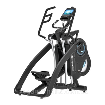
- Page 1 USER MANUAL – EN IN 19901 Elliptical Trainer inSPORTline inCondi ET2000i...
-
Page 2: Table Of Contents
CONTENTS SAFETY INSTRUCTIONS ........................3 IMPORTANT NOTES ..........................3 DIAGRAM ..............................5 PARTS LIST ............................7 ASSEMBLY MATERIAL ........................9 ASSEMBLY ............................10 PARTS LIST............................11 STEP 1 ............................... 13 STEP 2 ............................... 14 STEP 3 ............................... 15 STEP 4 ............................... 16 STEP 5 ............................... -
Page 3: Safety Instructions
SAFETY INSTRUCTIONS • To ensure the best safety of the exerciser, regularly check it on damages and worn parts. • If you pass on this exerciser to another person or if you allow another person to use it, make sure that that person is familiar with the content and instructions in these instructions. •... - Page 4 • Be sure to set up the exerciser in a dry and even place and always protect it from humidity. If you wish to protect the place particularly against pressure points, contamination, etc., it is recommended to put a suitable, non-slip mat under the exerciser. •...
-
Page 5: Diagram
DIAGRAM... -
Page 7: Parts List
PARTS LIST NAME NAME Main frame Ground wire SENSOR WIRE 900mm Ac power switch to power cord Sensor wire Axle Motor Power cord A3-1 Screw Flywheel Dc wire dc wire Flywheel cover Magnetic housing Sensor wire Front pedal support tube Sensor wire housing Motor push rod Screw... - Page 8 Foam spacer ring Ø 23 x 3tt x 150 Pedal housing (L) Foam grip Ø 23 x 3tt x 150 mm Pedal housing (R) Lower pedal support tube Sensor wire Pedal bracket (L) Sensor wire Pedal bracket (R) Sensor wire L1 Foot rest (L) Sensor wire L2 Foot rest (R)
-
Page 9: Assembly Material
ASSEMBLY MATERIAL NAME NAME SW001-B Screw M3 x 8 SW056-B Screw M4 x 12 SW004 Screw M4 x 15 SW057-B Screw M4 x 16 SW006 Screw M6 x 12 SW060 Screw M4 x 38 mm SW007 Screw M3 x 10 SW069-B Screw M8 x 16 SW013-B... -
Page 10: Assembly
ASSEMBLY Lay the box down flat so that the lid can be lifted. Unpack the handle bars, side support tubes, pedal support tube and owner’s manual. Remove the top polyfoam pieces 1 & 2 and finish up packing the console, console holder, central support tube, pedal support tube, and hardware bag, leaving the Main frame (A) and bottom polyfoam pieces 3 &... -
Page 11: Parts List
PARTS LIST... -
Page 13: Step 1
STEP 1 Central support tube 1. Remove the two pre-assembled screw (SW088-B) from the Main frame(A) and two screws (SW088-B) from the Central support tube (F1). 2. Connect the Central tube (F1) to the Main frame (A), use the previously removed screw (SW088-B) to attach them. -
Page 14: Step 2
STEP 2 Side cover sets 1. Assemble Cover (R2) with Cover (R1) and connect with screw (SW057-B) 2. Connect Cover (R1+R2) on the right side of Connecting tube (C2). 3. Connect the Cover (R3) on Tube (C2). 4. Connect the Cover (R4) on Tube (C2). •... -
Page 15: Step 3
STEP 3 Ride side connection tube 1. Connect the Tube (C2) to Main frame (A) according to VIEW A. 2. With Screws (SW039-B) M8x20 connect the Tube to the Frame. 3. Refer to the VIEW B, use 2 pieces Screw (SW099-B) M8x55 two Washers (W26-B) and the Iron to the bottom of the Frame bracket (F2) to attach the Tube 4. -
Page 16: Step 4
STEP 4 Connecting of left side tube and joint cover assembly 1. Connect the left Tube (C1) to the Frame (A). 2. Attach the Tube to the Frame on the top with the Screw (SW039-B) and on the bottom with two Screws (SW099-B), two washers (W26-B) to the Iron Support (F2). -
Page 17: Step 5
STEP 5 Pedal support 1. First secure the Screw (SW073-B), with Washer (W36-B) and Nuts (NT-NM12-B) according to VIEW C. 2. Connect the right Tube (B2) to the Main frame (A) and secure with Nut (NT-NM12-B), Washer (W36-B) and Screw (SW072-B) according to View D. 3. -
Page 18: Step 6
STEP 6 Handlebar assembly 1. Remove six pre-assembled Screws (SW014-B a NT014-B) from left Handlebar (E1). 2. Connect the left Handlebar (E1) to the Main frame (A) with screws (SW014-B a NT014-B) according to VIEW F. 3. Right Handlebar (E2) connect the same way. -
Page 19: Step 7
STEP 7 Console holder Connect Cables (D1 and D2) from Console holder (D) to the Cables (A1 and A2) from Main frame (A). With two screws (SW069-B) and two pre-assembled screws (DW069-B) connect the Console holder (D) to the Main frame (A). Tighten the screws according to VIEW G. With screw (SW047) connect the Bottle holder (H) to the Main frame (A). -
Page 20: Step 8
STEP 8 Console connection 1. Remove 4 screws (G1) from the back part of Console (G). 2. Connect cables (D1, D3, D14, 16) and cable (D4) to the Console. Make sure that the cables are properly connected, pushing the excessive cables into the Console holder (D). -
Page 21: Eliptical Transport
ELIPTICAL TRANSPORT Never move an elliptical yourself. Seek assistance from another person. Raise the rear to the front wheels and move slowly. POWER CORD 1. Connect the power cord to the frame and then to the power outlet. 2. Turn the switch ON. 0 –... -
Page 22: Resistance
RESISTANCE Once the console is turned on, you can use the buttons on the small handles to adjust the resistance. Press + LOAD to increase load, press –LOAD to reduce load. STRIDE LENGTH Depending on the user's needs, it is possible to change the stride length to 18 ", 20", 22 ", 24" and 26 " as shown on the LED controller. -
Page 23: Console
CONSOLE FUNCTIONS • Manual: Setup own program • Program: Choose program • WATT program: the machine increases or decreases the resistance so that the user performs the set performance (for example, increases the resistance when reducing the pedaling) • HRC program: resistance adjustment to keep the heart rate in optimal zone. User can choose 55%, 75%, 90%. -
Page 24: Buttons
BUTTONS QUICK START BUTTON: • When the console is in SLEEP mode, the quick start button can wake it up. • When the console is in STAND BY mode, the button can quick start the console. TFT display: • All operations are performed on touch display DISPLAY FUNCTION DESCRIPTION TIME Display shows values from 0:00 to 99:59... - Page 25 DISTANCE Display shows values from 0.0 to 60. You can setup value from 0 to 99, enter value on numerical keyboard Display is divided into 10 segments: • Max = 10 km, all segments • Default value without program is 1 segment = 1 km •...
- Page 26 USER User profiles U0 – U4. U0 – data are not saved after exercise U1 – U4 – saves data to profile You can choose AGE, HEIGHT, WEIGHT, USER NAME, GENDER • AGE: 1–99 (default value 25) • HEIGHT: 100-250 cm (default value 160 cm) 40–99 inches (default value 60 inches) •...
-
Page 27: Introduction
INTRODUCTION TURNING ON 1. The home screen will load after 30 seconds and will stay in standby mode (Pic. 1). You will see a panel of functions. Settings Time and calendar Quick start Community center Manual program Program Watt program HRC program... - Page 28 2. In home screen you can setup time and date. After entering the setting screen, please turn on Automatic time and date (Pic. 2) and choose your time zone 3. In standby mode, press QUICK START to turn on the quick start function. 4.
-
Page 29: Quick Start Function
5. Select COMMUNITY CENTER, MANUAL, PROGRAM, WATT CONSTANT, TARGET H. RATE to enter the function. QUICK START FUNCTION Press QUICK START. You will enter settings (Pic. 7). 1. If the RPM is higher than 15, SPEED, DISTANCE, RPM, CALORIES will be reset to zero after the value is exceeded and the countdown will start again. -
Page 30: Community Center
5. Press HOME to return to the home page. COMMUNITY CENTER 1. Press COMMUNITY CENTER to enter the multimedia functions. (Pic. 9) 2. Use additional options (Pic. 10) 3. After selecting, use the arrow keys to open the options HOME – QUICK START – VOLUME – BACK (Pic. -
Page 31: Manual Program
MANUAL PROGRAM 1. On home screen press MANUAL to enter settings 2. You can choose user U0 – U4. You will be displayed user information. (U0 is for guest, the data will not be saved). 3. You can setup AGE, HEIGHT, WEIGHT, GENDER and USER NAME. 4. -
Page 32: Programs
PROGRAMS 1. On home screen press PROGRAM to enter settings. (Pic. 16). 2. You can choose one of 12 programs. 3. Choose user U0-U4. The corresponding data is displayed. 4. You can setup TIME and choose AGE, HEIGHT, WEIGHT, GENDER and USER NAME. 5. -
Page 33: Watt Program
WATT PROGRAM 1. On the Home screen, select WATT CONSTANT to enter the settings (Pic. 19). 2. Press WATT to set the value (default value 125 W). 3. You can choose user U0 – U4. You will be displayed user information. (U0 is for guest, the data will not be saved). -
Page 34: Hrc Program
11. WATT will display current messages: • Too slow: Increase your speed. Current value <set value (1-25%) • Moderate: Keep your speed. Set value (1+25%) > Current watt value> Set value (1- 25%) • Too fast: Too fast. Current value> set value (1+25%) HRC PROGRAM 1. -
Page 35: Recovery Funkce
detected, the load is immediately reduced to 1 level. If no additional 30 seconds are detected, the program stops immediately. 10. If heart rate is not detected, you will be notified. 11. The console returns to the home screen if the heart rate is not detected for 30 seconds. 12. -
Page 36: Use Of Eleptical Trainer
USE OF ELEPTICAL TRAINER The elliptical trainer is a popular fitness machine, one of the newest and most effective home training machines. When you are exercising on an elliptical treadmill, your feet move along the elliptical curve. The elliptical treadmill is a frequent replacement for exercise bikes and treadmills because it is gentler for your joints. - Page 37 These Conditions of Warranty and Warranty Claims are an integral part of every Purchase Agreement made between the Seller and the Buyer. All Warranty Conditions are valid and binding, unless otherwise specified in the Purchase Agreement, in the Amendment to this Contract or in another written agreement.
- Page 38 26847264 VAT ID: CZ26847264 Phone: +420 556 300 970 E-mail: eshop@insportline.cz reklamace@insportline.cz servis@insportline.cz Web: www.inSPORTline.cz inSPORTline s.r.o. Headquaters, warranty & service center: Električná 6471, Trenčín 911 01, SK CRN: 36311723 VAT ID: SK2020177082 Phone: +421(0)326 526 701 E-mail: objednavky@insportline.cz reklamacie@insportline.cz servis@insportline.cz...
Need help?
Do you have a question about the inCondi ET2000i and is the answer not in the manual?
Questions and answers