Table of Contents
Advertisement
Quick Links
Advertisement
Table of Contents

Related Manuals for Insportline IN 13903


Summary of Contents for Insportline IN 13903
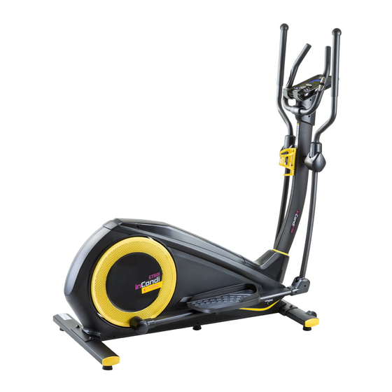
- Page 1 USER MANUAL – EN IN 13903 Elliptical inSPORTline inCondi ET50i...
-
Page 2: Table Of Contents
CONTENTS SAFETY INSTRUCTIONS ........................3 SAFETY NOTICE ............................ 3 PRE-ASSEMBLY NOTES ........................4 HARDWARE ............................4 PRODUCT DESCRIPTION ........................6 TECHNICAL INFORMATION ........................7 ASSEMBLY INSTRUCTIONS ......................... 7 WORKOUT TIPS ........................... 11 HALF-EXPLODED DRAWING ......................12 DRAWING FOR ASSEMBLY ........................ 14 PART LIST ............................. -
Page 3: Safety Instructions
SAFETY INSTRUCTIONS WARNING: This device has been designed and constructed to provide the maximal safety. But no certification or test can eliminate the risk of possible injury or damage totally. To avoid an injury, pay attention to following warnings and precautions. Read this manual carefully before first using and retain it for future reference. -
Page 4: Pre-Assembly Notes
Skin disease. Hyperpyrexia caused by sick (38 ℃ or over 38 ℃). Abnormal back bone or back bone bending. Pregnant women or women during period. Physical abnormality. Worsened body condition. WARNING: Before beginning any exercise program, consult your physician. This is especially important for persons older than 35 years or persons with pre-existing health problems. - Page 5 Name Specification Quantity Allen C.K.S. half thread screw M10x60x25 Ø10 Spring washer Ø10.5xR100xt2.0 Curved washer Allen C.K.S. half thread screw M8x20 Ø8 Spring washer Ø8.5xØ20xt1.5 Flat washer Hex self-locking nut Ø10 Flat washer Philips pan head full thread screw M4x16 Philips pan head full thread screw M4x10 Ø10x45xM6x20...
-
Page 6: Product Description
NOTICE: Gather the necessary tools and have them at hand. Make sure that you have enough of free space to assemble it. Pay attention to avoid an injury. The finished device put on a clear surface with enough of space for safe and comfortable using. -
Page 7: Technical Information
TECHNICAL INFORMATION Dimensions Unfolded: 1660x720x1580 mm Speed ratio Double way, ø280/9 kg Flywheel 1 – 32 Resistance level Stride length 420x200 mm NOTICE: We reserve the right to amend the product without prior notice. ASSEMBLY INSTRUCTIONS Step 1 Attach the front stabilizer (2) to the main frame (1) with curved washer (28), spring washer (27) and Allen C.K.S. - Page 8 Step 3 1. Attach the upright decoration strip (77) to the upper upright post (4). Take the upright post cover (15) from the main frame (1). Then attach to the upper upright post (4). 2. Connect motor communication wire (11) and console communication wire (12). 3.
- Page 9 Step 4 1. Assemble the waved spring washers (102) to the left and right axle (25). Then attach left body arm (5) and right body (6) to the left axle (25) and to the right axle (25). Use flat washer (31) and Allen C.K.S.
- Page 10 Step 6 1. Pass the handle pulse connection wire (13) through the upper upright post (4). Attach handlebars (9) to the upright post (4) with flat washer (31), spring washer (30) and half thread screw (29). 2. Attach bottle holder (24) to the upper upright post (4) with Philips pan head full thread screw (36).
-
Page 11: Workout Tips
Step 7 1. Connect console communication wire (12) with the interface of back console. Connect handle pulse communication wire (13) with console outset (14). 2. Attach the console (10) to the upper upright post (4) with screws (42). 3. Slide the left handlebar cover (22) and the right handlebar cover (23) out of the handlebar (9). Attach them to the upper upright post (4) with Philips pan head full thread screw (36). -
Page 12: Half-Exploded Drawing
HALF-EXPLODED DRAWING Name Description Main frame Front stabilizer Rear stabilizer Upper upright post Body arm L Body arm R Pedal supporter L... - Page 13 Pedal supporter R Handlebars Console Motor communication wire Console communication wire Handle pulse connection wire Console outset Upright post cover Body arm cover Body arm cover Front pedal supporter cover Front pedal supporter cover Rear pedal supporter cover Rear pedal supporter cover Handlebar cover L Handlebar cover R ø93x150...
-
Page 14: Drawing For Assembly
DRAWING FOR ASSEMBLY... -
Page 16: Part List
PART LIST Name Description 1 Main frame 2 Front stabilizer 3 Rear stabilizer 4 Upper upright post 5 Body arm (left) 6 Body arm (right) 7 Pedal supporter (left) 8 Pedal supporter (right) 9 Handlebars 10 Console 11 Motor communication wire 12 Console communication wire 13 Handle pulse connection wire 14 Console outset... - Page 17 ø8xø30xt3.0 50 Flat washer 51 Fixed idler ø15x30 52 Idler connecting shaft 53 Hex nut 54 Hex locking nut ø38x22 55 Tension pulley ø10 56 Circlip shaft 57 End cap 45x90xt1.5 58 Feet pad 59 Wheels ø8x33xM6x15 60 Allen C.K.S. hollow screw 61 Hex full thread screw M5x60 62 Hex nut...
-
Page 18: Display Functions
ø17 102 Waved spring washer 103 Hex nut 104 Allen full thread screw M10x20 105 Allen full thread screw (L) M8x20-L 106 Philips C.K.S. full head screw ST4x16 DISPLAY FUNCTIONS Item Description TIME It counts when the target has not been pre-set. The range is: 00:00 –... -
Page 19: Operation
Mode/Enter Confirm setting or selection. Reset Press and hold for 2 seconds. Computer will reboot and start from user setting. Reverse to the main menu during pre-set workout value or stop mode. Start/Stop Start or stop the workout. Recovery Test the heart rate recovery status. Body Fat In STOP mode, press it for body fat measuring. -
Page 20: Manual Mode
MANUAL MODE Press START in the main menu to start the workout in manual mode. 1. Use UP or DOWN (Encoder) to select workout program, choose MANUAL and push MODE/ENTER to get into. 2. Use UP or DOWN (Encoder) to set TIME (Pic. 8), DISTANCE (Pic. 9), CALORIES (Pic. 10), PULSE (Pic. -
Page 21: Advance Mode
Pic. 13 ADVANCE MODE 1. Use UP or DOWN (Encoder) top select workout program. Choose ADVANCE mode and press MODE/ENTER to get into. 2. Use UP or DOWN (Encoder) to select Advance program 1~4 (Pic. 14) and press MODE/ENTER to get into. 3. -
Page 22: Cardio Mode
CARDIO MODE 1. Use UP or DOWN (Encoder) to select workout program. Choose H.R.C. and press MODE/ENTER to get into. 2. Use UP or DOWN (Encoder) to set AGE (Pic. 16). 3. Use UP or DOWN (Encoder) to select 55% (Pic. 17), 75%, 90% or TAG (target H.R.). Default: 100. -
Page 23: Body Fat
Pic. 19 Pic. 20 BODY FAT 1. In the STOP mode, press the BODY FAT key to start body fat measurement. 2. Console will remind to input user GENDER (Pic. 21), AGE, HEIGHT, WEIGHT. Then it starts measuring. 3. During measuring, the user must grasp the grips with both hands. The LCD display will show “=”... -
Page 24: App
NOTED: 1. After 4 minutes without pedalling or pulse input, the console will enter power saving mode. Press any key to wake it up. 2. When the computer does not work properly, plug out the adaptor and plug it in again. 1. - Page 25 Neck exercises Tilt your head to the right and feel the tension in your neck. Slowly drop your head down to your chest in a semi-circle and then turn your head to the left. You will feel a comfortable tension in your neck again.
-
Page 26: Terms And Conditions Of Warranty, Warranty Claims
Touch toes Bend your trunk slowly forwards and try to touch your feet with your hands. Reach down as far as possible to your toes. Maintain this position for 20 – 30 seconds if possible. Exercise for the knees Sit on the floor and stretch out your right leg. Bend your left leg and place your foot on your right upper thigh. - Page 27 Warranty Conditions Warranty Period The Seller provides the Buyer a 24 months Warranty for Goods Quality, unless otherwise specified in the Certificate of Warranty, Invoice, Bill of Delivery or other documents related to the Goods. The legal warranty period provided to the Consumer is not affected. By the Warranty for Goods Quality, the Seller guarantees that the delivered Goods shall be, for a certain period of time, suitable for regular or contracted use, and that the Goods shall maintain its regular or contracted features.
- Page 28 VAT ID: CZ26847264 Phone: +420 556 300 970 E-mail: eshop@insportline.cz reklamace@insportline.cz servis@insportline.cz Web: www.insportline.cz INSPORTLINE s.r.o. Headquarters, Warranty & Service centre: Elektricna 6471, 911 01 Trencin, Slovakia CRN: 36311723 VAT ID: SK2020177082 Phone: +421(0)326 526 701 E-mail: objednavky@insportline.sk reklamacie@insportline.sk servis@insportline.sk Web: www.insportline.sk...
Need help?
Do you have a question about the IN 13903 and is the answer not in the manual?
Questions and answers