
Related Manuals for Insportline inCondi ET520i


Summary of Contents for Insportline inCondi ET520i
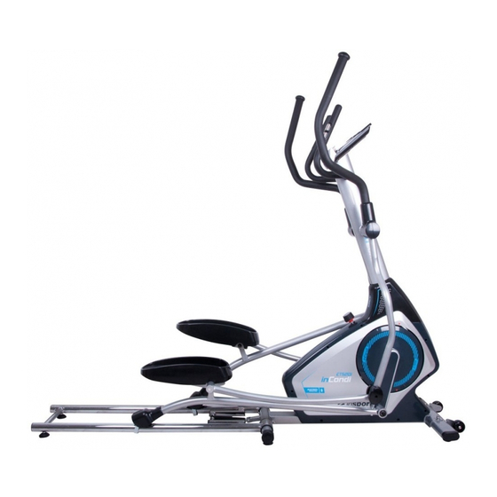
- Page 1 USER MANUAL – EN IN 9118 Elliptical Trainer inSPORTline inCondi ET520i Made in P.R.C...
-
Page 2: Table Of Contents
CONTENTS SAFETY CAUTION ..........................3 TOOL KIT ..............................4 EXPLODED VIEW ........................... 5 PARTS LIST ............................6 ASSEMBLY ............................10 STORAGE ............................. 20 TERMS AND CONDITIONS OF WARRANTY, WARRANTY CLAIMS ..........27... -
Page 3: Safety Caution
PREFACE This elliptical has been designed and constructed to provide maximum safety. Nevertheless, certain precautions should be taken when using exercise equipment. Read the whole manual before assembling and using the bicycle. The following safety precautions should also be observed: SAFETY CAUTION 1. -
Page 4: Tool Kit
IMFD TOOL KIT F-17: Allen Key(1) Box Spanner(1) F-2:HexboltM8*P1.0*20L (movabhandlebar)(4) F-13:SCREW M5*12L(8) F-6:Carriage Bolt F-5: Curved Washer 19*2T (4) M8*P1.25*40L (4) F-7:Flat washer for 19*2T bolt(4) F-14: F-4;lock nut for M8 bolt (6) IMFD F-9;FlatWasher £p 8 *£p 1 6*1T(2) F-12: F-8: Carriage Bolt F-11;... -
Page 5: Exploded View
EXPLODED VIEW D-25 D-26 D-30 D-31 D-29... -
Page 6: Parts List
PARTS LIST DESCRIPTION Q'TY Computer Screw Handlebar post set 1 (set) End cap for front handlebar Foam grip for front handlebar Hand pulse Screw Sleeve Axle for handlebar Flat washer Semicircle washer Cable wire (upper) B-10 Spring washer B-11 Screw B-12 Screw B-13... - Page 7 D-18 Axle for brake D-19 D-20 Nylon nut D-21 Flat washer D-22 Screw D-23 Flat washer D-24 Nylon nut D-25 Brake plate D-26 Felt D-27 Motor bracket 1 (set) D-29 Axle of gear box D-30 Screw D-31 D-32 Cable wire (lower) Eddy magnet assembly 1 (set) Screw...
- Page 8 Flat washer Bearing Axle for flywheel Bearing 1 (set) Bushing Front stabilizer set 1 (set) Foot cap for front stabilizer C-type ring Transportation wheel Sleeve Screw Adjustable foot cap Left pedal arm 1 (set) Right pedal arm 1 (set) Sleeve End cap Pedal connector Flat washer...
- Page 9 Screw Bushing Wave washer L-10 Nylon nut L-11 Flat Washer L-12 Bearing L-13 Bushing L-14 Bolt L-15 Crank arm connect base L-16 Screw L-17 Flat washer Rear stabilizer set Rear stabilizer Screw Rear stabilizer end cap Stabilizer adjusting cap Slide rail (left) Slide rail (right) Sleeve Cylinder...
-
Page 10: Assembly
Rear cover for upper handlebar Left cover for pedal arm Right cover for pedal arm Pedal ASSEMBLY BEFORE EVERYTHING It will affect your safety and the smoothness of this machine, as well as its life time. • Please check is there’s any parts missed. •... - Page 11 BUILD IT STEP 1 F-7:Flat washer for 8* 19*2T bolt(2) F-19¡ F Acorn nut M8(4) F-20:Carriage Bolt M8*P1.25*65L (2) F-5:flatwasher F-8:Carriage Bolt M8*P1.25*55L (2) 8* 19*2T (2) 1. Securely fasten the Front stabilizer (H) to the Main frame (D) by using 2 Flat washers (F-7), 2 Carriage screws (F-8), and 2 Nuts (F-19).
- Page 12 STEP 2 F-1;Flat washer for 8* 25*2T bolt(2) F-2:HexboltM8*P1.0*20L (movable handlebar)(2) F16: Box Spanner F-15: (2) 1. Assemble the Left crank arm (L-L) to Left crank (O-1) by using 1 Flat washer (F-1), 1 Nylon screw (F-2), and 1 Cover for screw (F-15). 2.
- Page 13 STEP 3 F-16:Box Spanner Assembly the Covers (L-6) on sliders with Screws (L-7) and fix the Lockers (M-15) with Screws & Washers (L-16 & L-17).
- Page 14 STEP 4 F-3:Curved Washer B-8: Curved Washer 20* 30*0.3T(2) for M8 bolt (2) F-1;Flat washer for B-7:Flat washer for B-11:SCREW 8* 25*2T bolt(2) 8* 19*2T bolt(4) M8*P1.25*16L(6) F17: Allen Key B-10: Spring Washer 8(6) F-16:Box Spanner 1. Connect the Cable wire (upper) (B-9) to the Cable wire (lower) (D-32). 2.
- Page 15 STEP 5 F-4;lock nut for M8 bolt (2) F-9;FlatWasher 8* 16*1T(2) F-10; 16*36.5L bolt(2) F-11; allen bolt M8*P1.25*50L(2) I-5:Flat washer for 8* 19*2T bolt(6) I-6:SCREW M8*P1.25*16L(6) I-4:(2) F17: Allen Key F-16:Box Spanner 1. Attach the Left pedal arm (I-L) to the Left crank arm (L-L), and then fasten it with 1 Pedal connector (I-4), 3 Flat washers (I-5), and 3 Screws (I-6).
- Page 16 STEP 6 F-13:SCREW M5*12L(8) F-14;FlatWasher 6* 16*1T(8) F17: Allen Key F-14 Assemble the Pedals (P-5) with 8 Screws (F-13) and 8 Flat washers (F-14).
- Page 17 STEP 7 F17: Allen Key F-12:SCREW M5*8L(4) Assemble Left & Right cover for pedal arms (P-3 & P-4) with 4 Screws (F-12).
- Page 18 STEP 8 F 17: Allen Key Bo x S pa nn er F- 6: C arriage Bolt M 8*P1.25*40L (4) F -4;loc k nut for M 8 bolt ( 4) 1. Install the Left upper handlebar (C-L) to the Left lower handlebar by using 4 Nylon nuts (F-4), 4 Semicircle washers (F-5), 4 Carriage screws (F-6).
- Page 19 STEP 9 F17: Allen Key Box Spanner 1. Plug the Cable wire (upper) (B-9) and Hand pulse wire (B-13) onto the back of Computer (A). 2. Install the Computer (A) to the computer panel which is welded on the top of the handlebar post. Fix the computer with 4 Screws (A-1).
-
Page 20: Storage
STORAGE FOLDING 1. Find the knob in the front the chain cover and fix the knob with clockwise direction (make the two marks” arrow” in one line). 2. Lift up the rail between the R/L rails and finish the folding. - Page 21 UNFOLD FOR USE 1. Push forward the rails. 2. Kick the foldable cylinder which area is sticked with the following yellow label by feet. 3. Continue to kicking and push back until the cylinder is fully change angel as following. 4.
- Page 22 5. Find the knob in the front the chain cover and fix the knob with anti-clockwise direction.
- Page 23 DISPLAY FUNCTIONS ITEM DESCRIPTION TIME Workout time displayed during exercise. Range 0:00 ~ 99:59 SPEED Workout speed displayed during exercise. Range 0.0 ~ 99.9 DISTANCE Workout distance displayed during exercise. Range 0.0 ~ 99.9 CALORIES Burned calories during workout display. Range 0 ~ 999 PULSE Pulse bpm displayed during exercise.
- Page 24 WORKOUT SELECTION Press UP and Down to select workout Manual Beginner Advance Sporty Cardio Watt MANUAL MODE Press START in main menu may start workout in manual mode. 1) Press UP or DOWN to select workout program, choose Manual and press Mode to enter. 2) Press UP or DOWN to preset TIME, DISTANCE, CALORIES, PULSE and press MODE to confirm.
- Page 25 ADVANCE MODE 1) Press UP or DOWN to select workout program, choose Advance mode and press Mode to enter. 2) Press UP or DOWN to preset TIME. 3) Press START/STOP key to start workout. Press UP or DOWN to adjust load level. 4) Press START/STOP key to pause workout.
- Page 26 WATT MODE 1) Press UP or DOWN to select workout program, choose WATT and press Mode to enter. 2) Press UP or DOWN to preset WATT target. (default: 120) 3) Press UP or DOWN to preset TIME. 4) Press START/STOP key to start workout. Press UP or DOWN to adjust Watt level. 5) Press START/STOP key to pause workout.
-
Page 27: Terms And Conditions Of Warranty, Warranty Claims
The manual will be updated from time to time, the consumer can get the newest version by scanning the QR code or link to the website as below. Fit Hi Way INSTRUCTION : NOTE: 1. Once console is connected to tablet via Bluetooth, the console will power off. 2. - Page 28 otherwise specified in the Purchase Agreement, in the Amendment to this Contract or in another written agreement. Warranty Conditions Warranty Period The Seller provides the Buyer a 24 months Warranty for Goods Quality, unless otherwise specified in the Certificate of Warranty, Invoice, Bill of Delivery or other documents related to the Goods. The legal warranty period provided to the Consumer is not affected.
- Page 29 VAT ID: CZ26847264 Phone: +420 556 300 970 E-mail: eshop@insportline.cz reklamace@insportline.cz servis@insportline.cz Web: www.insportline.cz INSPORTLINE s.r.o. Headquarters, Warranty & Service centre: Elektricna 6471, 911 01 Trencin, Slovakia CRN: 36311723 VAT ID: SK2020177082 Phone: +421(0)326 526 701 E-mail: objednavky@insportline.sk reklamacie@insportline.sk servis@insportline.sk Web: www.insportline.sk...
Need help?
Do you have a question about the inCondi ET520i and is the answer not in the manual?
Questions and answers