Table of Contents
Advertisement
Quick Links
Advertisement
Table of Contents

Subscribe to Our Youtube Channel
Related Manuals for Insportline IN 163 Atlanta


Summary of Contents for Insportline IN 163 Atlanta
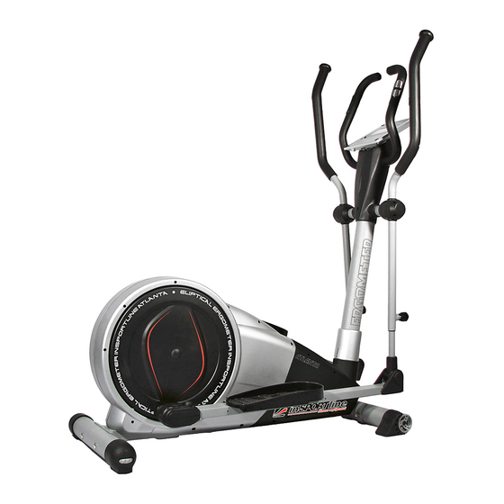
- Page 1 Manual - EN IN 163 inSPORTline Atlanta Elliptical...
- Page 2 Safety Instructions • To ensure the best safety of the exerciser, regularly check it on damages and worn parts. • If you pass on this exerciser to another person or if you allow another person to use it, make sure that that person is familiar with the content and instructions in these instructions.
- Page 3 Important Notes • Assemble the exerciser as per assembly instructions and be sure to only use the strucutral parts provided with the exerciser and designed for it. Prior to the assembly, make sure the contents of the delivery is complete by referring to the parts list of the assembly and operating instructions. •...
- Page 4 Exploded drawing...
- Page 5 Part List Q’ty Part No. Description Specification Main frame stabilizer D76x1.5Tx480L carriage bolt M8x1.25x93L,8.8 Adjustable foot cap D76*86 Left transfer foot cap D76*120L Right transfer foot cap D76*120L curve washer D22xD8.5x1.5T spring washer D15.4*D8.2*2.0T domed nut M8x1.25x15L allen bolt M8x1.25x20L,8.8 handlebar post pedal welding set left swing support...
- Page 6 magnetic system D274*138L right upper foot cover 115x95x43 side cap D36*14 bolt M8x1.25x20 fixed ring D38*D26.5*7 round discs bearing #6004ZZ round cross screw ST4x1.41x15L anti-loose nut 3/8"-26UNFx6.5T FE flat washer D30*D10*4.1T flat washer D50*D10*2T small spacer D10*D14*3T insert plug D31.8xD28.5x82L flat washer D20*D11*2T plastic flat washer...
- Page 7 anti-loose nut M10*1.25*10T left front chain cover right front chain cover upper protective cover flat washer D23*D17*1.2T flat washer D21*D8.5*1.5T upper universal cover 125*90*39 lower universal cover 125*90*39 smaller adjustable knob D38xM16x1.5xD8x23 front computer base 380*150*50 rear computer base 340*150*50 adaptor round cross screw ST4x1.41x15L...
-
Page 8: Checklist (Contents Of Package)
CHECKLIST (CONTENTS OF PACKAGE) 72L&R 84&85 21L&R 81&82 12 7 D22*D8.5*1.5T D15.4*D8.2*2T M8*1.25*93L 4 20 M8*1.25*20L M8*1.25*15L M6*1*45L D14*D6.5*0.8T ST4*15L M8*1.25*100L M5*0.8*10L M8*1.25*8T... - Page 9 STEP 1 (x4) (x4) M6*1*45L D14*D6.5*0.8T 1) Assemble the front stabilizer (2) and rear stabilizer (19) onto the main frame (1) by using the carriage bolt (3), the curved washer (6), the spring washer (7) and domed nut (8). 2) Adjust the proper height by turning the wheel of rear foot cap (4). 3) Assemble the left and right pedal (21L&21R) on the pedal supporting tube (11) by using the carriage bolt (20),flat washer (73) and knob (89) 4) 3 optional positions for the pedals...
- Page 10 STEP 2 (x4) 1) Suggest assembling this step by two persons. 2) First, lift up the cover for handlebar post (78) like fig. (a), then connect computer cable (29) with the cable of motor (30) like fig.(b&c) 3) Insert the handlebar post (10) on the main frame and tighten it by using the curved washer (6), the spring washer (7) and the allen bolt (9).
- Page 11 STEP 3 (x2) Assemble the left and right fixed handlebar (72L &72R) on the handlebar post (10) by using the Allen bolt (16) , the curved washer (6), the spring washer (7) and the domed nut (93).
- Page 12 STEP 4 (x4) 1) Connect the computer cable (29) and cable of hand pulse sensor (75) with the computer (64), then fix the computer (64) on the handlebar post (10) by using the screws. 2) Put the bolt cap (22) and bolt cap (59) on the bolt.
- Page 13 STEP 5 (x8) (x6) ST4*15L (x2) M5*10L 1) Fix the upper and lower cover for universal joint (81&82) on the universal joint (32) by using the screw (44). 2) Fix the front and rear cover for handlebar post (84&85) on the handlebar post (10) by using the screw (44&87).
-
Page 14: Key Function
INSTRUCTION MANUAL OF SM7650 【KEY FUNCTION】 MODE In stop mode, MODE is to confirm all exercise data setting, and enter into program. In stop mode, press the button back to main menu RESET Hold on pressing for 2 seconds, computer will reboot. START/STOP To start or stop exercise. -
Page 15: Manual Mode
USER PERSONAL DATA SETTING (U1~U4) The console will enter to the USER setting .User may press UP or DOWN key to select U1 to U4 (Drawing 2).By pressing MODE key to enter personal data setting, SEX(Drawing 3) , AGE (Drawing 4), HEIGHT (Drawing 5), WEIGHT (Drawing 6) and press MODE key for confirmation. -
Page 16: User Mode
Drawing 11 H.R.C MODE After enter H.R.C. mode, press UP or DOWN key to select different target from 55%, 75%, 90% and TARGET. Press MODE key to confirm. (Drawing 12) The heart rate value will be calculated according to the age user inputs. (Drawing 12) USER MODE After enter USER mode, the first column of the profile is blinking, user may press UP or DOWN key and... - Page 17 <REFERENCE> B.M.I. (Body mass index) integrated B.M.I LOW/MED MEDIUM MED/HIGH SCALE RANGE <20 20-24 24.1-26.5 >26.5 *** B.M.I. (Body Mass Index)*** BMI is to determine whether the user is fatness, but it is not 100% correct. BODY FAT <European>: — ▲...
Need help?
Do you have a question about the IN 163 Atlanta and is the answer not in the manual?
Questions and answers