
Related Manuals for Stanley Supreme Deluxe 90 Induction


Summary of Contents for Stanley Supreme Deluxe 90 Induction
- Page 1 Supreme Deluxe 900 Induction User Guide & Installation & Service Instructions U110464 - 01...
-
Page 3: Table Of Contents
Tips on Cooking with the Timer Circuit Diagram: Hob General Oven Tips Circuit Diagram: Oven Cooking Table Technical Data Cleaning Your Cooker Hotplate Efficiency Data Oven Data Glide-out Grill Control Panel and Doors Ovens Cleaning Table Stanley Supreme Deluxe 90 Induction U110464-01... -
Page 5: Before You Start
1. Before You Start... Ventilation Your cooker should give you many years of trouble-free cooking if installed and operated correctly. It is important CAUTION: The use of a cooking appliance results in that you read this section before you start, particularly if you the production of heat and moisture in the room in have not used an induction cooker before. - Page 6 Always be certain that the controls are in the OFF position Fig. 1-1 when the oven is not in use, and before attempting to clean the cooker. Take care when touching the marked cooking areas of the hob. When the oven is on, DO NOT leave the oven door open for longer than necessary, otherwise the ArtNo.324-0001 Steam burst control knobs may become very hot.
-
Page 7: Hob Care
DO NOT use water on grease fires and never pick Fig. 1-3 up a flaming pan. Turn off the controls and then smother a flaming pan on a surface unit by covering the pan completely with a well fitting lid or baking tray. -
Page 8: Cooker Overview
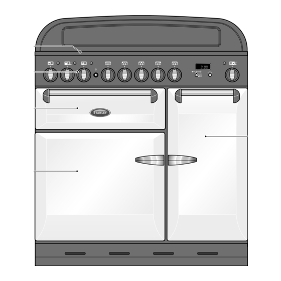
2. Cooker Overview DocNo.020-0006 - Overview - 100DF - Prof+ Fig. 2-1 Your induction cooker (Fig. 2-1) has the following features: Fig. 2-2 5 induction cooking zones A control panel A glide-out grill A multi-function oven A tall fan oven The Hob Use only pans that are suitable for induction hobs. - Page 9 The very best pans have bases that are very slightly curved Fig. 2-4 up when cold (Fig. 2-3). If you hold a ruler across the bottom you will see a small gap in the middle. When they heat up the Max: 1.85 kW Max: 1.85 kW Max: 1.85 kW...
- Page 10 Residual Heat Indicator, H Automatic heat-up time at Power level 100% (min:sec) After use, a cooking zone will remain hot for a while as heat dissipates. When a cooking zone is switched off the residual 0:48 heat indicator symbol [H ], will appear in the display. This 2:24 shows that the cooking zone temperature is above 60 °C and may still cause burns.
- Page 11 Low Temperature Setting, L1/L2 Fig. 2-8 A & B linked This function should only be used when heating from cold. Each cooking area is equipped with 2 low temperature settings: L1 will maintain a temperature of about 40 °C – ideal for •...
-
Page 12: The Glide-Out Grill
The Glide-out Grill Fig. 2-9 CAUTION: This appliance is for cooking purposes only. It must not be used for other purposes, for example room heating. CAUTION: Accessible parts may be hot when the grill is in use. Young children should be kept away. Open the door and pull the grill pan carriage forward using the handle (Fig. -
Page 13: The Ovens
The Ovens Function The clock must be set to the time of day before the left- Rapid response To preheat the oven faster than normal hand oven will work. See the following section on ‘The Clock’ for instructions on setting the time of day. To thaw small items in the oven without Defrost heat... - Page 14 Fan Oven Browning Element This function operates the fan and the heating This function uses the element in the top of the oven element around it. An even heat is produced only. It is a useful function for the browning or throughout the oven, allowing you to cook large finishing of pasta dishes, vegetables in sauce, amounts quickly.
- Page 15 Operating the Ovens Fig. 2-12 Fan Oven Turn the oven knob to the desired temperature (Fig. 2-12). The oven indicator light will glow until the oven has reached the temperature selected. It will then cycle on and off during cooking. Multi-function Oven The multi-function oven has two controls: a function selector and a temperature setting knob (Fig.
-
Page 16: The Clock
The Clock Fig. 2-15 ArtNo.300-0005 2BC Setting the Time of Day minute minder setting The 2-knob LCD clock is shown in (Fig. 2-15). When the clock is first connected, the display flashes ( 0.00 ) and ( alternately. To set the time, turn and hold the Timer knob to the clock symbol [ ... - Page 17 The ‘stop time’ is displayed, followed by ‘AUTO’ . Set the oven Fig. 2-23 Fig. 2-24 to the cooking temperature you need. Turn the Timer knob to the ‘Auto’ setting. ArtNo.301-0012 2BC Art No. 301-0011 2BC Activating the key lock 2 Activating the key lock 1 When your cooking is finished, the beeper sounds.
-
Page 18: Accessories
Accessories Shelf guard Fig. 2-28 Oven Shelves Flat shelf In addition to the flat shelves, your cooker is supplied with a drop shelf (Fig. 2-28). The drop shelf increases the possibilities for oven shelf spacing. Removing and Refitting the Oven Shelves Front The shelf has a small kink on either side (Fig. -
Page 19: Cooking Tips
3. Cooking Tips Using Your Induction Cooker General Oven Tips If you have not used an induction cooker before please be The wire shelves should always be pushed firmly to the back aware of the following: of the oven. • Make sure that the pans you have or buy are suitable Baking trays with food cooking on them should be placed for use on the induction hob. -
Page 20: Cooking Table
4. Cooking Table DocNo.031-0004 - Cooking table - electric & fan single cavity The oven control settings and cooking times given in the table below are intended to be used Top (T) AS A GUIDE ONLY. Individual tastes may require the temperature to be altered to provide a ArtNo.050-0007 preferred result. -
Page 21: Cleaning Your Cooker
5. Cleaning Your Cooker Isolate the electricity supply before carrying out any major Fig. 5-1 cleaning. Allow the cooker to cool. NEVER use paint solvents, washing soda, caustic cleaners, biological powders, bleach, chlorine based bleach cleaners, coarse abrasives or salt. DO NOT mix different cleaning products –... -
Page 22: Glide-Out Grill
Glide-out Grill Fig. 5-2 Before you remove any of the grill parts for cleaning, make sure that they are cool, or use oven gloves. The grill pan and trivet should be washed in hot soapy water. Alternatively, the grill pan can be washed in a dishwasher. After grilling meats or any foods that soil, leave to soak for a few minutes in the sink immediately after use. -
Page 23: Control Panel And Doors
Control Panel and Doors Fig. 5-6 Avoid using any abrasive cleaners including cream cleaners. For best results, use a liquid detergent. The same cleaner can also be used on the doors, or alternatively, using a soft cloth wrung out in clean hot soapy water –... -
Page 24: Cleaning Table
Cleaning Table Cleaners listed (Table 5.1) are available from supermarkets or electrical retailers as stated. For enamelled surfaces use a cleaner that is approved for use on vitreous enamel. Regular cleaning is recommended. For easier cleaning, wipe up any spillages immediately. Hotplate Part Finish... -
Page 25: Troubleshooting
6. Troubleshooting DocNo.050-0001 - Troubleshooting - Induction GENERIC Interference with and repairs to the hob MUST NOT The cooling fan be carried out by unqualified persons. Do not try The induction hob incorporates a cooling fan. This to repair the hob as this may result in injury and cooling fan is active when either the grill or ovens damage to the hob. - Page 26 Food is cooking too slowly, too quickly, or burning Fig. 6-1 Cooking times may differ from your previous oven. Check that you are using the recommended temperatures and shelf positions – see the oven ArtNo.324-0005 Oven light bulb cooking guide. Then adjust the settings according to your own individual tastes.
- Page 27 The oven light is not working Fig. 6-3 The bulb has probably blown. You can buy a replacement bulb (which is not covered under the guarantee) from most electrical stores. Ask for an Edison screw fitting 15 W 230 V lamp, FOR OVENS (Fig.6-1). It must be a special bulb, heat resistant to 300 °C.
-
Page 28: Installation
INSTALLATION Check the appliance is electrically safe when you have finished. 7. Installation Dear Installer You will need the following equipment to complete the cooker installation satisfactorily: Before you start your installation, please complete the details • Multimeter: For electrical checks. below, so that, if your customer has a problem relating to You will also need the following tools: your installation, they will be able to contact you easily. -
Page 29: Positioning The Cooker
INSTALLATION Check the appliance is electrically safe when you have finished. Positioning the Cooker Fig. 7-1 Fig. 7-1 and Fig. 7-2 show the minimum recommended distance from the cooker to nearby surfaces. 75 mm 75 mm The cooker should not be placed on a base. 650 mm The hotplate surround should be level with, or above, any adjacent work surface. -
Page 30: Repositioning The Cooker Following Connection
INSTALLATION Check the appliance is electrically safe when you have finished. Lowering the Two Rear Rollers Fig. 7-5 To adjust the height of the rear of the cooker, first fit a 13 mm spanner or socket wrench onto the hexagonal adjusting nut (Fig. -
Page 31: Fitting The Handles
INSTALLATION Check the appliance is electrically safe when you have finished. Fitting the Handles Fig. 7-7 The handles for the grill door and tall oven will require fitting as follows: Open the door. To keep the door open, either place a suitable weight on it (grill door only) or have someone hold it. -
Page 32: Electrical Connection
INSTALLATION Check the appliance is electrically safe when you have finished. Electrical Connection Fig. 7-11 The cooker must be installed by a qualified electrician, in accordance with all relevant British Standards/Codes of Practice (in particular BS 7671), or with the relevant national and local regulations. -
Page 33: Final Fitting
INSTALLATION Check the appliance is electrically safe when you have finished. Final Fitting Fig. 7-13 Fitting the 2-piece Plinth Fit the inner plinth to the bottom front of the cooker using the 5 screws provided (3x M5 screws in the lower edge, 2x No.8 screws in the each end) (Fig. -
Page 34: Circuit Diagrams
8. Circuit Diagrams ArtNo.095-0003 - Circuit diagram - 90 induction Circuit Diagram: Hob Earth N(6) On terminal block N(4) On terminal block Induction unit Hob display L(2) L(3) ArtNo.083-0011 - IN G5 2-phase - Circuit diagram On terminal block w/br Interface w/br w/br... -
Page 35: Circuit Diagram: Oven
Circuit Diagram: Oven P095199 P095199 P038434 w br b The connections shown in the circuit diagram are for single-phase. The ratings are for 230 V 50 Hz. Code Description Code Description Code Colour Clock / timer Grill front switch Blue Right hand oven front switch Grill energy regulator Brown... -
Page 36: Technical Data
DocNo.107-0023 - Technical data - 110DF - Classic DL 9. Technical Data INSTALLER: Please leave these instructions with the User. DATA BADGE LOCATION: Cooker back, serial number repeater badge below oven door opening. COUNTRY OF DESTINATION: GB, IE. Connections Electric 230 / 400 V 50 Hz Dimensions Overall height... -
Page 37: Hotplate Efficiency Data
Hotplate Efficiency Data Brand Stanley Model Identification Supreme Deluxe Size Type Induction Type of Hob Induction Number of electric zones Zone 1 - Ø cm 18.5 Heating Technology Energy Consumption (ECElectric cooking) - Wh/kg Zone 2 - Ø cm 15.5... -
Page 38: Oven Data
Oven Data Brand Stanley Model identification Supreme Deluxe Type of oven Electric Mass Number of cavities Left-hand Efficiency Fuel type Electric Cavity type Multifunction Power - conventional Power - forced air convection Volume Litres Energy consumption (electricity) - conventional kWh / cycle 1.08... - Page 39 Notes...
- Page 40 Waterford Ireland Tel: (051) 302300 Fax: (051) 302315 With Waterford Stanley’s policy of continuous product improvement, the Company reserves the right to change specifications and make modifications to the appliance described at any time. w w w.water fo rdstanley.co m...
Need help?
Do you have a question about the Supreme Deluxe 90 Induction and is the answer not in the manual?
Questions and answers