Table of Contents

Subscribe to Our Youtube Channel
Related Manuals for Perfect Aire 8000PPAC


Summary of Contents for Perfect Aire 8000PPAC
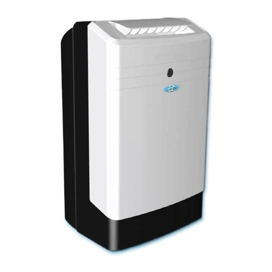
- Page 1 Your Source for Home Comfort (8,100 & 10,000 BTU) PORTABLE AIR CONDITIONER USER MANUAL FOR MODELS: 8000PPAC 10000PPAC Before using your portable air conditioner, please read this manual carefully and keep it for future reference, along with your receipt.
-
Page 2: Table Of Contents
CONTENTS SAFETY PRECAUTIONS ..................2 IDENTIFICATION OF PARTS................3 AIR CONDITIONER FEATURES................5 OPERATING INSTRUCTIONS ................6 INSTALLATION INSTRUCTIONS ................ 7 CARE AND MAINTENANCE ................12 TROUBLESHOOTING TIPS ................13 This manual provides the information needed for proper use and maintenance of this air conditioner. -
Page 3: Safety Precautions
SAFETY PRECAUTIONS Never do this Always do this Do not operate your air conditioner in a wet room such as a Your air conditioner should be used in such a way bathroom or laundry room. that it is protected from moisture (i.e. condensation, Do not touch the unit with wet or damp hands or when splashed water, etc.). -
Page 4: Identification Of Parts
IDENTIFICATION OF PARTS • Exhaust hose 1 Set • Flat mouth adaptor • Window slider kit with bolt Vent Exhaust Flat Mouth Bolt Window • Vent joint Joint Hose Adaptor Slider Kit • Foam Seal 1 Piece • Wall exhaust adaptor A* 1 Set •... - Page 5 IDENTIFICATION OF PARTS (CONTINUED) Operation Panel Horizontal Louver Blade (manual) Remote Signal Receptor Caster Carrying Handle (both sides) Fig. 2 Upper Air Filter (behind the grille) Air Outlet Power Cord Outlet Air Intake Drain Outlet Air Intake Lower Air Filter Fig.
-
Page 6: Air Conditioner Features
AIR CONDITIONER FEATURES ELECTRONIC CONTROL OPERATING INSTRUCTIONS Before you begin, thoroughly familiarize yourself with the control panel and remote control and all its functions, then follow the symbol for the functions you desire. The unit can be controlled by the unit control panel alone or with the remote control. NOTE: This manual does not include Remote Control Operations, see the Remote Control Instructions packed with the unit for details. -
Page 7: Operating Instructions
OPERATING INSTRUCTIONS COOL operation SLEEP operation - Press the "MODE" button until the "COOL" In this mode the selected temperature will indicator light comes on. increase by 2 C 30 minutes after the mode - Press the ADJUST buttons "∧" or "∨" to is selected.The temperature will then increase select your desired room temperature. -
Page 8: Installation Instructions
INSTALLATION INSTRUCTIONS Fig. 6 Vertical window Window Slider Kit Minimum:2.22 ft (67.5 cm) Fig. 7 Maximum:4.04 ft (123 cm) NOTE: If the window opening is less than 2.22 ft, cut the extension piece (see Fig. 9) shorter so the kit properly fits in the window opening. Only cut if Horizontal window absolutely necessary. - Page 9 INSTALLATION INSTRUCTIONS (CONTINUED) See Fig. 10. Fig. 10 sill. See Fig. 11. See Fig. 12. 26.5” - 48” Fig. 11 Window sill See Fig. 13. Fig. 12 Window sill Fig. 13...
- Page 10 INSTALLATION INSTRUCTIONS (CONTINUED) See Fig. 14. Fig. 14 height of height of sill. See Fig. 15. 26.5” - 48” See Fig. 16. Fig. 15 See Fig. 17. Fig. 16 Fig. 17...
-
Page 11: See Fig.
INSTALLATION INSTRUCTIONS (CONTINUED) Exhaust hose installation: Fig.18 The exhaust hose and adaptor must be installed or removed Flat Mouth in accordance with the usage mode. Adaptor COOL or AUTO mode Install Hose Vent Joint Exhaust Hose FAN or DRY mode Remove Hose Note: Flat mouth adaptor and vent joint must be threaded counter clockwise onto the exhaust hose. -
Page 12: Water Drainage
INSTALLATION INSTRUCTIONS (CONTINUED) Water drainage: During dehumidifying modes, remove the drain plug from the back of the unit and install the drain connector (5/8” universal female mender) with 3/4” hose (locally purchased). For models without drain connector, just attach the drain hose to the hole. Place the open end of the hose directly over the drain area in your basement floor. -
Page 13: Care And Maintenance
CARE AND MAINTENANCE CARE AND MAINTENANCE IMPORTANT: Air filter (slide out) 1) Be sure to unplug the unit before cleaning or servicing. 2) Do not use gasoline, thinner or other chemicals to clean the unit. 3) Do not wash the unit directly under a tap or using a hose. It may cause electrical danger. -
Page 14: Troubleshooting Tips
TROUBLESHOOTING TIPS Before calling for service, please review the chart below. Issue Possible Solutions • Be sure unit is not too large or too small for the area of the room. • Verify that all doors, windows, curtains and any other openings are closed off. Verify nothing is obstructing the airflow to/from the unit and louvers such as curtains, etc. - Page 15 Your Source for Home Comfort Distributed by: Perfect Aire, LLC 5151 Belt Line Rd. Suite 878 Dallas, TX 75254 877-365-6274 www.perfectaire.us Specification and performance data is subject to change without notice. Printed in PRC...
Need help?
Do you have a question about the 8000PPAC and is the answer not in the manual?
Questions and answers