Advertisement
Quick Links
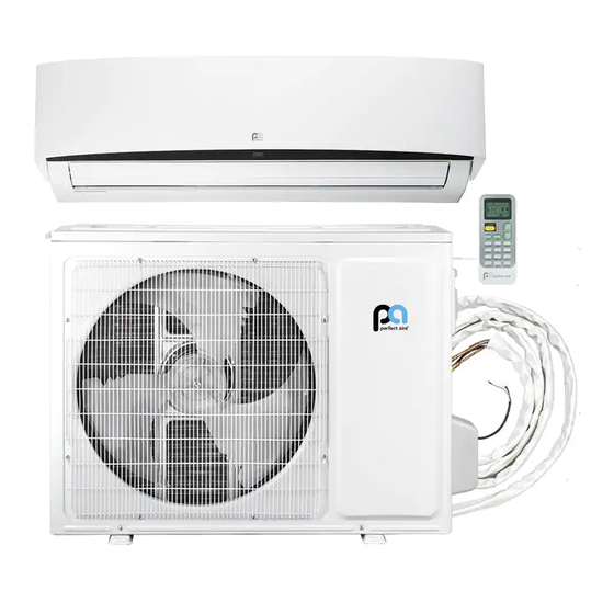
USER INSTALLATION
MANUAL
FOR MODELS:
3PAMSHQC09
3PAMSHQC12
3PAMSHQC18
3PAMSHQC24
3PAMSHQC36
SINGLE-ZONE
DUCTLESS MINI SPLIT SYSTEM
Before using your air conditioner, please read this
manual carefully and keep it for future reference,
along with your receipt. Specifications and performance
data is subject to change without notice.
36K
9 – 24K
Advertisement


Need help?
Do you have a question about the 3PAMSHQC09 and is the answer not in the manual?
Questions and answers