Webasto Thermo Top C Installation Instructions Manual
For volvo 2003 xc 90
Hide thumbs
Also See for Thermo Top C:
- Installation instructions manual (56 pages) ,
- Operating instructions manual (40 pages) ,
- Operating and installation instructions (39 pages)
Table of Contents
Advertisement
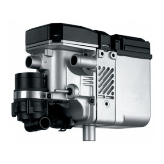
Water Heater Unit
Thermo Top C Additional Heater
4
3
4
1
2
5
Legend for Figure 1
1 Thermo Top C -B heater unit
2 Blade-type fuse holder
3 Exhaust muffler
4 Combustion-air intake pipe
5 Telestart receiver, Thermo Call
6 Metering pump
7 Gateway control unit
WARNING!
Hazard warning:
Incorrect installation or repair of Webasto heating and cooling systems may cause a fire or result
in the emission of carbon monoxide, which can be fatal. Serious or fatal injuries can be caused
as a result.
Specialist company training, technical documentation, specialized tools and equipment are
required to install and repair Webasto heating and cooling systems.
NEVER attempt to install or repair Webasto heating or cooling systems if you have not
successfully completed the company training and thereby acquired the required technical skills,
or if you do not have access to the required technical documentation, tools and equipment
needed to carry out correct installation and repairs.
ALWAYS follow all Webasto installation and repair instructions and observe all warnings.
Webasto does not accept any liability for defects and damage that are attributable to installation
by untrained staff.
Ident. No. 9010409D_EN
6
7
1
Fee Euro 10
e1
00 0002
Installation Instructions
Volvo XC 90
Gasoline
From model year 03
For left-hand drive vehicles only
See Page 2 for validity
Note:
Only in conjunction with Webasto Gateway!
Only in conjunction with the corresponding
Volvo vehicle software!
For combination with Telestart and/or Thermo
Call, the Volvo AEM must also be used with the
corresponding software!
© Webasto AG
Advertisement
Table of Contents

Related Manuals for Webasto Thermo Top C


Summary of Contents for Webasto Thermo Top C
-
Page 1: Installation Instructions
7 Gateway control unit WARNING! Hazard warning: Incorrect installation or repair of Webasto heating and cooling systems may cause a fire or result in the emission of carbon monoxide, which can be fatal. Serious or fatal injuries can be caused as a result. -
Page 2: Table Of Contents
XC 90 Thermo Top C Table of Contents Volvo XC 90 Combustion-Air Intake Pipe Validity Exhaust System Heater Unit/Installation Kit Coolant Connection for 2.5 and 3.0 Liter Engine 18 Foreword Coolant Connection for 3.2 Liter Engine Special Tools Fuel Connection... -
Page 3: Heater Unit/Installation Kit
XC 90 Thermo Top C Heater Unit/Installation Kit Quantity Description Volvo Order No.: Thermo Top C -B water heater unit with vehicle-specific delivery scope 12000093 Depending on vehicle equipment, if not present: Quantity Description Volvo Order No.: Volvo heater software in accordance with equipment... -
Page 4: Preliminary Work
XC 90 Thermo Top C Preliminary Work General Preliminary Work - Remove years that do not apply from the duplicate label - Attach duplicate label (type label) in an easily visible place - Apply the filling station sticker in an easily visible... -
Page 5: Heater Unit Installation Location
XC 90 Thermo Top C Electrical Connections Preparing wiring harness for all vehicles - Cut off brown (br) wire (4) to fan relay - Insulate wire section to wiring harness and tie back - Cut off green/white (gn/ws) wire (5) from fan relay... - Page 6 XC 90 Thermo Top C Routing wiring harness for gateway control unit - Route wiring harness (1) behind battery to left-hand side to REM. - Route white (ws) 0.5 mm wiring harness (branch) to REM at rear left. - Route wiring harness further under side trim to front, along original vehicle wiring harness in left-hand door sill into footwell on driver's side.
-
Page 7: Gateway Wiring Harness Up To 2004 Model
XC 90 Thermo Top C - Connect green/white (gn/ws) wire end (4) to connector and green/white (gn/ws) wiring harness (3) from gateway with connector (crimp and shrink) - Route green (gn) wire (8) from gateway through cable pass throughs (1,2) -
Page 8: Gateway Wiring Harness From To 2005 Model
XC 90 Thermo Top C - Connect green/white (gn/ws) wire (1) from gateway wiring harness to green/white (gn/ws) wire (2) from connector C, Pin 32 as shown in wiring diagram. - Produce connection according to wiring diagram with included connector. - Page 9 XC 90 Thermo Top C - Connect connector (2) to wiring harness of additional heater - Connect connector (1) to Telestart receiver (see Telestart option) - Connect positive wire (8 mm dia. ring eye) (1) to positive support point (2)
-
Page 10: Gateway Wiring Harness
XC 90 Thermo Top C Gateway wiring harness Stecker Stecker Telestart Vorwahluhr Stecker Thermo Call (Option) 12 4... -
Page 11: Wiring Diagram
XC 90 Thermo Top C Wiring diagram Webasto Volvo St 01 gn/ws Legend for wiring diagram: Webasto components Volvo components Colors and symbols Heater unit TT-C/E Gateway white Connector on heater Connector on gateway green unit Connector on gateway blue... -
Page 12: Remote Option (Telestart)
XC 90 Thermo Top C Remote option (Telestart) Note: The installation location of the Telestart antenna (1) is on the windshield at the lower left! Produce connections according to general installation instructions and fasten lines with cable ties. - Clean and degrease bonding surface on windshield... -
Page 13: Thermo Call Option
XC 90 Thermo Top C - Lay receiver (3) on trim as shown and copy hole pattern 1,2) - Drill two 5.5 mm dia. holes - Fasten receiver and bracket with two M5x12 bolts, washers, spring lockwashers and nuts - Connect antenna cable and Telestart connector to... -
Page 14: Installing Heater Unit
XC 90 Thermo Top C Installing Heater Unit Preparing installation location - Lay on included template (1) as shown - Copy hole pattern (2,3,4) - Drill three 7.0 mm dia. holes - Pry off central cover (1) on heater unit... - Page 15 XC 90 Thermo Top C - Fasten 30 mm spacer nut (1) on stud bolt Installing heater unit - Drill 7 mm dia. hole (1) as shown 22 mm 12 mm - Connect wiring harness of heater unit - Fasten premounted heater unit with four M6x20 bolts ( 1,2,4,5), A7.4 washers and flanged nuts...
-
Page 16: Combustion-Air Intake Pipe
XC 90 Thermo Top C - Angle down perforated bracket (4) by 45° at center - Fasten water pump (1) on existing hole on engine support with M6x85 bolt, rubber-coated p-clamp (4), 15 mm spacer nut (5), perforated bracket (4), A7.4 washer and flanged nut - Drill out hole to 7 mm dia. -
Page 17: Exhaust System
XC 90 Thermo Top C Exhaust system Exhaust pipe WARNING: Ensure sufficient spacing to hoses and lines when installing exhaust system. - Cut exhaust pipe (1) and exhaust-pipe end section (2) to length as shown - Mount 370 mm long exhaust pipe (1,4) on exhaust... -
Page 18: Coolant Connection For 2.5 And 3.0 Liter Engine
XC 90 Thermo Top C Integration in Water Circuit Note: Tighten all hose clamps to 2.0 + 0.5 Nm. Any coolant running off should be collected with an appropriate container! Install hoses so that they are kink-free. The connection of the heater unit "in series" (inline) in the vehicle coolant circuit is described in the following. - Page 19 XC 90 Thermo Top C - Cut off original vehicle coolant hose (1,2) as shown - Connect cut-off 90° elbow (1) to engine outlet, turn toward front in driving direction and fasten with hose clamp - Connect coolant hose, 900 mm long (1) to heater- unit coolant outlet with 180°...
- Page 20 XC 90 Thermo Top C - Connect 500 mm long coolant hose (1) with 90° elbow to water-pump coolant inlet, route to cutting point and fasten with hose clamp as shown - Connect 500 mm long coolant hose (1) from water- pump coolant inlet and original vehicle 90°...
-
Page 21: Coolant Connection For 3.2 Liter Engine
XC 90 Thermo Top C Coolant connection for 3.2 liter engine Cut off hose sections from included coolant hoses as shown in Figure 55 and 56: 1 x 1,070 mm long + 90° elbow (1) (from engine outlet to water-pump coolant inlet... - Page 22 XC 90 Thermo Top C - Cut off original vehicle coolant hose as shown. Discard hose elbow. Loosen coupling (1) and pull off. - Connect shortened hose (2) to coupling (1) with 18/20 connecting pipe (4) and hose clamp (3).
- Page 23 XC 90 Thermo Top C - Mount coolant hose, 1,070 mm long (1) on water- pump coolant inlet with 90° elbow and fasten with hose clamp (2) - Route 1,070 long coolant hose (1) below frame side member to firewall.
- Page 24 XC 90 Thermo Top C - Fasten premounted angle bracket (1) on original vehicle threaded hole with M8x20 (5) bolt and spring lockwasher as shown. - Fasten angle bracket (3) on original vehicle threaded hole with M8x20 (4) bolt and spring lockwasher as shown.
-
Page 25: Fuel Connection
XC 90 Thermo Top C Fuel Connection WARNING: Open the vehicle's fuel tank cap, ventilate the tank and then re-close the fuel tank cap. Catch any fuel running off with an appropriate container. Route fuel line so that it is protected against stone impact. - Page 26 XC 90 Thermo Top C - Push included heat protection hose (1) onto Mecanyl fuel line and wiring harness of metering pump - Route Mecanyl fuel line and wiring harness of metering pump along original vehicle fuel lines on firewall to underbody...
-
Page 27: Removing Fuel
XC 90 Thermo Top C - Fasten perforated bracket (2) with metering pump (1) and fuel filter (4) with original vehicle bolt (3; 64/5) as shown in Figure 63 and Figure 64 - Route Mecanyl fuel line (6; 64/2) and wiring harness of metering pump (5;... - Page 28 XC 90 Thermo Top C - Push molded hose (1) as far as possible onto standpipe and connection piece at end with inside 8.0 mm dia. - Fasten molded hose (1) on connection piece with 12 mm hose clamp (4)
-
Page 29: Installing Software
- Connect vehicle battery. - Set vehicle clock. - Fill and bleed coolant circuit according to vehicle manufacturer’s specifications. - Switch on Webasto heater, see "Operating and Maintenance Instructions" - Cut out wheel-well inner panel as shown if necessary Note:... -
Page 30: Template For Bracket
XC 90 Thermo Top C Template for Bracket Ø 7mm Original vehicle hole Ø 7mm Ø 7mm 100 mm Scale 1:1 Compare the size of the printed version with dimension lines. Permitted tolerance a maximum of 2%. Set the printer settings to “no margin” or “minimize margins”... -
Page 31: Operating Instructions For End Customer
XC 90 Thermo Top C Operating Instructions for End Customer Please remove page and add to the vehicle operating instructions. Additional heater can be switched with following heater controls: - Steering column lever over original vehicle display in instrument panel (clock/direct start), - "Telestart"...
Need help?
Do you have a question about the Thermo Top C and is the answer not in the manual?
Questions and answers