Webasto Thermo Top C Installation Instructions Manual
Thermo top series coolant heater
Hide thumbs
Also See for Thermo Top C:
- Installation instructions manual (56 pages) ,
- Operating instructions manual (40 pages) ,
- Operating and installation instructions (39 pages)
Table of Contents
Advertisement
Coolant Heater
Thermo Top Series
7
6
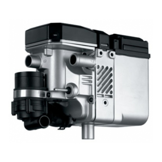
Legend
1 Electrical Harness sockets
2 Coolant Outlet
3 Fuel Inlet
4 Exhaust
5 Coolant Inlet
6 Coolant Circulation Pump
7 Combustion Air Intake
Special Tools
- Hose Clamping pliers
- Torque Wrench
1.1 Scope and Purpose - - - - - - - - - - - - - - - - - 5
1.3 Symbol Identification - - - - - - - - - - - - - - - 6
1.4 General References - - - - - - - - - - - - - - - - 7
1.5 Preparation - - - - - - - - - - - - - - - - - - - - - - 7
Installation
2
Electrical Overview - - - - - - - - - - - - - - - - - 8
2.2 Electrical Harness - - - - - - - - - - - - - - - - - - 9
2.3 Fuse Tap Connection - Relay K-1 - - - - - - - 9
2.4 Routing Harnesses Through Bulkhead - - - - 9
2.5 Timer Installation - - - - - - - - - - - - - - - - - 10
2.6 Integration into the Blower System - - - - - 10
3
Heater Mounting - - - - - - - - - - - - - - - - - 12
3.1 Recommended Locations- - - - - - - - - - -
4
Fuel System - - - - - - - - - - - - - - - - - - - - - 16
4.1 Fuel Extraction - - - - - - - - - - - - - - - - - - - 16
4.2 Fuel Supply - - - - - - - - - - - - - - - - - - - - - 18
- - - - - - - - - - - - - - - - - - - - - 18
4.4 Fuel Pump Installation - - - - - - - - - - - - - - 19
DOC P/N 5000778C
KIT P/N 5000777B
Light Duty Generic Installation
1
Instructions
2
3
4
5
4.5 Integration into the Fuel System - - - - - - -19
5
Combustion Air Supply- - - - - - - - - - - - - -21
5.1 Air Intake Silencer Installation - - - - - - - - -21
6
Exhaust System - - - - - - - - - - - - - - - - - - -22
7
Integration into the Coolant System - - - - -22
7.1 Repositioning the Circulation Pump - - - - -23
8
Power and Ground Connections - - - - - - -24
8.1 GroundConnection - - - - - - - - - - - - - - - -24
8.2 Power Connection - - - - - - - - - - - - - - - -24
9
Concluding Work - - - - - - - - - - - - - - - -25
9.1 Final Inspection (use installation checklist) -25
9.2 Initial Start-up - - - - - - - - - - - - - - - - - - - -28
12
9.3 Concluding Work - - - - - - - - - - - - - - - - -28
10 Heater Lockout Reset Procedure - - - - - - -29
Electrical Harness Schematic - Part 1 - - - - - - - -30
Electrical Harness Schematic - Part 2 - - - - - - - -31
Programming the 24 Hour Digital Timer- - - - - -33
Printed in USA
Advertisement
Table of Contents

Related Manuals for Webasto Thermo Top C


Summary of Contents for Webasto Thermo Top C
-
Page 1: Table Of Contents
4.4 Fuel Pump Installation - - - - - - - - - - - - - - 19 Programming the 24 Hour Digital Timer- - - - - -33 DOC P/N 5000778C KIT P/N 5000777B Printed in USA Webasto Thermo & Comfort N.A., Inc. - Page 2 • Only genuine Webasto parts may be used. See also Webasto air and water heat- ers accessories catalogue. • Product produces temperatures high enough to ignite surrounding combustible materials such as inflammable liquids, gases, vapor, and other combustible matter.
-
Page 3: Foreword
Failure to comply with all installation instructions is a misuse of Webasto products. The same applies for repairs without using genuine Webasto service parts. This will void the coolant heaters “official Marks of Conformity.”... -
Page 4: Symbol Identification
1.3 Symbol Identification 1.3.1 Symbols that define sections in manual Fuel Mechanical Preparation Exhaust Electrical Combustion Air Intake Coolant General Symbol Descriptions Refer to Webasto or Manufacturer Manual Warning Attention Caution Line of Sight/Item Location on Vehicle Flammable or Combustible... -
Page 5: General References
Thermo Top C 1.4 General References – Bare body parts, for example around drilled holes, must be treated with anti-corrosive coating. – Secure hoses, cables and wiring harnesses with cable ties and fit protective hoses around them at chafing points. -
Page 6: Electrical Overview
Thermo Top C 2 Electrical Overview ATTENTION Ensure wiring and wiring harnesses are securely fastened to the vehicle. If not described differently, securing of wiring is done with cable ties to the vehicle’s own wiring harnesses. 2.1 Universal Electrical Harness Description... -
Page 7: Electrical Harness
Fuse must remain hot with the ignition in the “ON” position only. ATTENTION •The blue fuse tap wire signals the Webasto heater of an ignition cycle, returning vehicle blower control to the driver’s discretion. •You may need to route the fuse tap wire into the inte- rior of the vehicle. -
Page 8: Timer Installation
Thermo Top C 2.5 Timer Installation CAUTION Check behind panels for obstructions before drilling holes. ATTENTION Before installing the timer, please confirm the installation location with the customer. Affix supplied template to panel. Drill 10 mm (25/64 in.) and 2.5 mm (3/32 in.) holes where indicated on template. - Page 9 2.6.2 3-Relay HVAC Harness Connec- Webasto Vehicle tions NOTE: It is permissible to cut excess length from Webasto HVAC wiring harnesses to fit the application. “ ” Cut motor wires where indicated by – (1) Chassis ground – (2) Splice green wire to green wire –...
-
Page 10: Heater Mounting
Recommended heater locations: Engine Compartment, Front Fenders (above splash shields), frame rail, etc... ATTENTION The coolant pump on the Webasto heater is not of the self-priming type. To ensure automatic venting of the heater and circulation pump mount the heater in the lowest protected area possible. - Page 11 Thermo Top C ATTENTION Observe torque specifications. Install heater mounting bracket with three EJOT screws. Tighten EJOT screws to 10 Nm (88.5 lb.-in.). – (1) Heater mounting bracket – (2) EJOT screws Fig. 13 Drill a 7mm (17/64 in.) hole through front bumper support as shown in Figure 14.
- Page 12 3.1.2 Sample Heater Installation (Ford F-150) ATTENTION The Webasto Auxiliary Coolant Heater is to be installed behind left front head lamp assembly affixed to the front core support as shown in Figure 17. – (1) Webasto Coolant Heater and Bracket.
- Page 13 – (2) Heater Bracket – (3) Coolant Inlet Hose – (4) Coolant Outlet Hose – (5) Straight Fuel Line Connector – (6) Exhaust Tube Fig. 21 ATTENTION Top view of heater installed in vehicle. – (1) Webasto Auxiliary Coolant Heater Fig. 22...
-
Page 14: Fuel System
Failure to follow these installation instructions and their content will result in the refusal of all liability on the part of Webasto. The same also applies to repairs not carried out properly or using parts other than genuine spare parts 4.1.2... - Page 15 3Standpipe Fig. 25 4.1.3 Fuel line Tee Adapter There are various sizes and shapes of fuel line adapters available from Webasto (see Figure 26). CAUTION A fuel line adapter should not be installed after the vehicle fuel pump. Fuel line pressure from the vehicle fuel pump could overcome the Webasto heater dosing pump, causing excessive fuel delivery to the heater.
-
Page 16: Fuel Supply
4.3 Fuel Lines The special fuel line supplied in the kit is the only fuel line approved by Webasto for heater installation. Ensure the fuel line from the metering pump to the heater is not routed in a downward pitch and is secured to the vehicle. -
Page 17: Fuel Pump Installation
Thermo Top C ATTENTION •Ensure the fuel lines are fully seated within the fuel line couplers and any 90 degree bends are not buckled. Refer to Figure 29. •Tighten all fuel line clamps to 1.0 - 1.4 Nm (8.8 - 12.4 lb.-in.) - Page 18 Thermo Top C ATTENTION When selecting a location for standpipe installation, ensure to leave enough room for electrical connections and float arm operation. Drill a 5/16 in. hole through the fuel sender where shown in Figure 32. – (1) Fuel sender –...
-
Page 19: Combustion Air Supply
Thermo Top C 5 Combustion Air Supply ATTENTION • The combustion air must never be drawn from the occupant area of the vehicle. If the heater is installed in an enclosed housing, a vent hole of at least 3 cm (1.2 in.) is required •... -
Page 20: Exhaust System
• To ensure proper venting, route coolant hoses below coolant filler cap. As a rule, the coolant hose supplied by Webasto should be used. If any other coolant hose is used it must conform to DN standard 73411. Ensure coolant hoses are routed in a way that prevent kinks and allow for proper venting. -
Page 21: Repositioning The Circulation Pump
Thermo Top C Fig. 40 7.1 Repositioning the Circulation Pump The circulation pump can be mounted at the location provided on the heater or be integrated into the coolant circuit, away from the heater. Ensure flow through the heater is correct (coolant outlet at the top / coolant inlet at the bottom) or the heater will malfunction. -
Page 22: Power And Ground Connections
Thermo Top C 8 Power and Ground Connections 8.1 Ground Connection Use existing ground point to attach the control harness ground (brown wire). – (1) Existing vehicle ground – (2) Control harness ground Fig. 42 8.2 Power Connection Attach the control harness power lead (red wire) to the positive stud or the battery positive post. -
Page 23: Final Inspection Initial Start-Up And Concluding Work
Thermo Top C 9 Final Inspection Initial Start-up and Concluding Work Connect battery ground terminal 9.1 Final Inspection HEATER MOUNTING Complete (Yes/No/Comments) Is the heater installation safely secure / rigid? (Ensure that all bracket bolts are tight) Is there a safe clearance from heat generating Components? (I.e. - Page 24 Verify the correct fuses are in the specified locations per the installation manual. Ensure heater and vehicle fuse boxes are closed and secure. Was the Webasto fuse block installed in a location protected from water and / or moisture? Ω) Ensure blower motor resistor (1.0...
- Page 25 Thermo Top C COMBUSTION AIR INTAKE Complete (Yes/No/Comments) Is the combustion air intake drawing fresh air from a non-turbulent location? (i.e. not in direction of travel) Ensure air intake system is securely fastened. HEATER FUNCTION Complete (Yes/No/ Comments) Ensure heater starts and runs for a minimum of 20 minutes.
-
Page 26: Initial Start-Up
1 Set interior temperature control to maximum heat position (hot), fan speed between low and maximum, and switch to defrost mode. 2 Start the vehicle engine and run on fast idle for 5 minutes to purge any remaining air from the Webasto heater and coolant system. While the engine is running check: •... -
Page 27: Heater Lockout Reset Procedure
If you have any questions, contact our technical support team at (800) 860-7866 or via email at: info-us@webasto.com. ATTENTION – The engine coolant must be below 86 °F (30 °C) before the Webasto heater will attempt to start. -
Page 28: Electrical Harness Schematic - Part 1
Thermo Top C Electrical Harness Schematic - Part 1, Heater Control... -
Page 29: Electrical Harness Schematic - Part 2
Thermo Top C Electrical Harness Schematic - Part 2, HVAC Blower Control... -
Page 30: Heater Plumbing Schematic - Inline Method - -32
Thermo Top C Heater Plumbing Schematic - Inline Method... -
Page 31: Programming The 24 Hour Digital Timer
Thermo Top C Programming the 24-Hour Digital Timer Programming the 24 Hour Digital Timer with 3 Time Settings Time / Remaining Time Ventilation Mode Indicator * ventilation mode not available on BlueHeat Heater Operation Indicator Reverse Forward (viewing (viewing the time) - Page 32 Thermo Top C Programming the 24 Hour Digital Timer with 3 Time Settings Continued: Program Start of Heating. Press the button. Press the “Forward” or “Reverse” buttons within 10 seconds until the required time for starting heating operation is displayed.
- Page 33 Please list any other comments, concerns, or suggestions. Please provided contact information below. Name: Company Name: City / State: Phone: Mail To: Email: Webasto Thermo & Comfort N.A., Inc. Attn: Technical Services 15083 North Road Fenton, MI 48430 Phone: (800) 860-7866 Fax: (810) 593-6001...
- Page 34 Thermo Top C...
- Page 35 Thermo Top C...
-
Page 36: Webasto Thermo & Comfort N.a., Inc
Webasto Thermo & Comfort N.A., Inc. Technical Assistance Hotline USA: (800) 860-7866 Outside USA: (810) 593-6000 www.webasto.us Org. 08/2005 Rev. 02/2018 P/N 5000778C www.techwebasto.com...
Need help?
Do you have a question about the Thermo Top C and is the answer not in the manual?
Questions and answers