Webasto Thermo Top E Installation Instructions Manual
For toyota 2005 corolla verso
Hide thumbs
Also See for Thermo Top E:
- Installation documentation (41 pages) ,
- Installation instructions manual (36 pages) ,
- Manual (31 pages)
Table of Contents
Advertisement
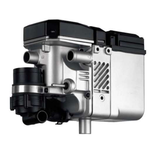
Water Heater Unit
Thermo Top E Additional Heater
Thermo Top C Additional Heater
Thermo Top P Additional Heater
Installation Instructions
Toyota Corolla Verso
Diesel
from Model Year 2005
Left-hand drive vehicle
WARNING!
Hazard warning:
Incorrect installation or repair of Webasto heating systems may cause a fire or result
in the emission of carbon monoxide, which can be fatal. Serious or fatal injuries can
be caused as a result.
Specialist company training, technical documentation, specialized tools and
equipment are required to install and repair Webasto heating and cooling systems.
NEVER attempt to install or repair Webasto heating or cooling systems if you have not
successfully completed the company training and thereby acquired the required
technical skills, or if you do not have access to the required technical documentation,
tools and equipment needed to carry out correct installation and repairs.
ALWAYS follow all Webasto installation and repair instructions and observe all
warnings.
Webasto does not accept any liability for defects and damage that are attributable to
installation by untrained staff.
Ident. No.: 1310512B_EN
e1
00 0003
e1
00 0002
e1
00 0104
Fee Euro 10
Feel the drive
© Webasto AG
Advertisement
Table of Contents

Related Manuals for Webasto Thermo Top E


Summary of Contents for Webasto Thermo Top E
-
Page 1: Installation Instructions
Specialist company training, technical documentation, specialized tools and equipment are required to install and repair Webasto heating and cooling systems. NEVER attempt to install or repair Webasto heating or cooling systems if you have not successfully completed the company training and thereby acquired the required technical skills, or if you do not have access to the required technical documentation, tools and equipment needed to carry out correct installation and repairs. -
Page 2: Table Of Contents
Toyota Corolla Verso Table of Contents Validity Remote option (Telestart) Heater Unit/Installation Kit Remote option (Thermo Call) Foreword Preparing installation location General Instructions Installing heater unit Special Tools Coolant connection Explanatory Notes on Document Combustion air Preliminary Work Fuel Connection Heater unit installation location Exhaust system Preparing electrical system... -
Page 3: Heater Unit/Installation Kit
1310307B Heater unit recommended for the respective vehicle class: Vehicle Heater unit Compact car Thermo Top E Mid-size car, station wagon Thermo Top C Full-size car, van, offroader Thermo Top P The selection of the heater unit is based on the passenger compartment size of the vehicle and the... -
Page 4: Explanatory Notes On Document
Specific risk of damage to components. Specific risk of fire or explosion. Reference to general installation instructions of Webasto components or to the manufacturer's vehicle- specific documents. Reference to a special technical feature. The arrow in the vehicle icon indicates the position on the vehicle and the angle. -
Page 5: Preliminary Work
Toyota Corolla Verso Preliminary Work WARNING! - Disconnect the battery "earth" or "ground" connection. - Depressurize the cooling system. - Copy the factory number from the original type label to the duplicate type label. - Remove years that do not apply from the duplicate label. - Attach the duplicate label (type label) in the appropriate place. -
Page 6: Preparing Electrical System
Toyota Corolla Verso Preparing electrical system Only with automatic air- sw 0,75mm² conditioning Wiring sections 1 and 3 will be required later 2000 for fan controller. Wiring sections 2 and 6 will be required later Cutting for connecting fuse F4. wires to length rt 0,75mm²... -
Page 7: Electrical Connections
Toyota Corolla Verso Electrical Connections Fuse holder, K3 relay Digital timer Fuse F4 and K3.1 relay only with automatic air- 1 Digital timer conditioning! 1 Battery holder 3 Fuse holder preassembled 2 7 mm dia. hole, M6x20 bolt, preassembled fuse holder, M6 flanged nut Do not install the metering pump cable harness until later together with fuel pipe along the original... -
Page 8: Fan Controller For Manual Air Conditioning
Toyota Corolla Verso Fan controller for manual air conditioning Webasto Toyota rt/ws Wiring dia- gram for manual air condition- Webasto components Toyota components Colors and symbols Heater unit Fan fuse 25 A fuse Fan motor white Fan relay Fan relay... - Page 9 Toyota Corolla Verso Connection on 2-pin connector DF on fuse and relay carrier. 1 Fuse and relay carrier 2 Connector DF Fan con- troller for manual air condition- Connection on 2-pin connector DF on fuse and relay carrier. Make connections as shown in wiring diagram with connectors (yellow) provided.
-
Page 10: Automatic Air-Conditioning Fan Controller
Wiring Webasto Toyota diagram ws/sw 4² 4² 0,75² 0,75² K3.1 St 01 12/14 Webasto components Toyota components Colors and symbols Heater unit TT-C Fan motor 25 A fuse Fan relay white Additional 3 A fuse Fan controller black Fan relay... - Page 11 Toyota Corolla Verso Connection on 3-pin connector DF from fuse and relay carrier. Produce connections as shown in wiring diagram with 3x distributor and tab receptacles provided. 1 Connector DF 2 Black (sw) wire to fan motor Fan control Remove wire 4 from connector DF. Insulate wire 4 and 6 and tie back.
- Page 12 Toyota Corolla Verso Connector of A/C control panel equipment- dependent with automatic air-conditioning Connector of A/C control panel, 24-pin Connector of A/C control panel equipment- dependent with two-zone automatic air- conditioning Connector of A/C control panel, 28-pin...
-
Page 13: Remote Option (Telestart)
Toyota Corolla Verso Remote option (Telestart) 1 M5x16 bolt, bracket, M5 flanged nut on existing hole 2 Receiver, mounted on bracket Installing receiver 1 Antenna Installing antenna... -
Page 14: Remote Option (Thermo Call)
Toyota Corolla Verso Remote option (Thermo Call) 1 Receiver, M5x20 bolts, flanged nuts, washer [4x each] 2 Lower footwell cover on front passenger side Installing receiver 1 Antenna Installing antenna 1 Pushbutton 2 Blind cap 3 Center console Installing push button... -
Page 15: Preparing Installation Location
Toyota Corolla Verso Preparing installation location 36 mm Picture shows bracket with Index F! 2 Bracket 1 7 mm dia. hole 46 mm Hole in bracket Copy hole pattern at Position 3 [2x]. Remove bracket again. Drill 9.1 mm dia. hole at Position 3 [2x] in frame side member and mount rivet nuts. -
Page 16: Installing Heater Unit
Toyota Corolla Verso Installing heater unit Connect wiring harness for heater unit before installation. Insert two washers between heater unit and bracket at Position 3 . Tighten EJOT screws to 10 Nm! Installing 1 Bracket heater unit 2 Ejot screw [2x] 3 Ejot screw Ejot screw bolt, tightening torque 10 Nm! 2 Bracket... -
Page 17: Coolant Connection
Toyota Corolla Verso Coolant connection WARNING! Tighten all hose clamps to 2.0 + 0.5 Nm. Any cold water running off should be collected using an appropriate container! Install hoses so that they are kink-free. Unless specified otherwise, always fasten using cable ties. Position hose clamps and spring band clamps so that no other hose can be damaged. - Page 18 Toyota Corolla Verso b = 770 mm c = 600 mm Hose A = 90° molded hose, included Hose C with long 90° elbow Discard section X Cutting coolant hoses to length Push braided protection hoses onto hose B and C . Push on heat shrink plastic tubing and shrink.
- Page 19 Toyota Corolla Verso Disconnect original vehicle hose 2 from connection piece of engine outlet. Original vehicle spring clip 1 will be reused! 1 Original vehicle spring clip 2 Hose from engine outlet to heat exchanger inlet Cutting point Mount hose A on connection piece of engine outlet and fasten with original vehicle spring clip 1 .
-
Page 20: Combustion Air
Toyota Corolla Verso Combustion air 1 Combustion-air intake pipe 2 27 mm dia. hose clamp Installing intake pipe 6 mm dia. hole 1 in plastic part of cooling air duct if not yet installed. Hole for cable tie 1 Combustion-air intake pipe 3 Combustion-air intake muffler 2 Cable tie Fastening... -
Page 21: Fuel Connection
Toyota Corolla Verso Fuel Connection CAUTION! Open the vehicle's fuel tank cap, ventilate the tank and then re-close the tank lock. Catch any fuel running off with an appropriate container. Install fuel line and metering-pump wiring harness so that they are protected against stone impact. Unless specified otherwise, always fasten using cable ties. - Page 22 Toyota Corolla Verso Fasten metering pump on existing hole on fuel tank with rubber-coated p-clamp, silentblock and flanged nut [2x]. 1 Rubber-coated p-clamp, silentblock, large diameter washer, flanged nut [2x] 2 Metering pump Installing metering pump Fuel line from heater unit on pressure side of metering pump [side with connector].
-
Page 23: Exhaust System
Toyota Corolla Verso Exhaust system 1 Exhaust pipe a = 240 mm 2 Exhaust end section b = 230 mm Preparing exhaust Discard section X pipe 2 Muffler 1 M6x20 bolt, spring lockwasher Installing muffler 3 Exhaust muffler 1 Exhaust pipe 2 Hose clamp [2x] Installing exhaust... - Page 24 Toyota Corolla Verso 2 Exhaust end section 1 Hose clamp 3 Red (rt) rubber isolator with groove, pushed on Installing exhaust section First position red (rt) rubber isolator 2 on exhaust end section 3 from below, then insert with groove in underride protection 1 . Align end cap of exhaust end section 3 flush on red (rt) rubber isolator 2 as shown.
-
Page 25: Final Work
- Attach the "Switch off additional heater before refueling" sticker to the left-hand B-pillar. Feel the drive Webasto AG Postfach 80 - 82132 Stockdorf, Germany - Hotline +49- (0)1805-932278 Hotfax +49-(0)395-5592-353 - http://www.webasto.de Printed in Germany 12/07 Printing: Steffen... -
Page 26: Operating Instructions For End Customer
Toyota Corolla Verso Operating Instructions for End Customer Please remove page and add to the vehicle operating instructions. Note: We recommend matching the heating time to the driving time. Heating time = driving time Example: For a driving time of approx. 20 min. (in one direction), we recommend not exceeding a switch-on time of 20 min.
Need help?
Do you have a question about the Thermo Top E and is the answer not in the manual?
Questions and answers