Webasto Thermo Top C Operating Instructions Manual
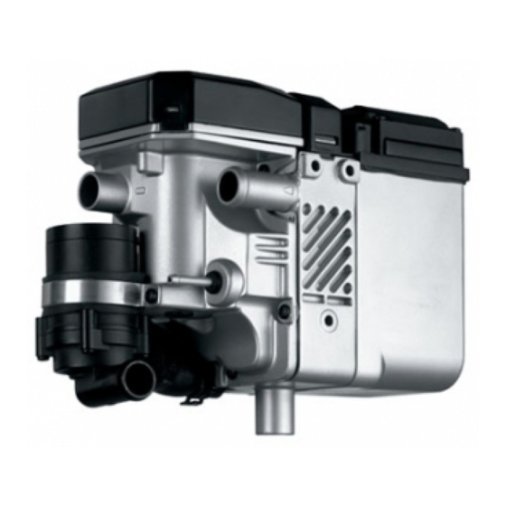
Coolant heater
Hide thumbs
Also See for Thermo Top C:
- Installation instructions manual (56 pages) ,
- Operating and installation instructions (39 pages) ,
- Manual (8 pages)
Advertisement
Quick Links
Coolant Heater
Thermo Top (TTC)
Operating Instructions
Installation Instructions
Improper installation or repair of Webasto heating and cooling systems can cause fire or the
leakage of deadly carbon monoxide leading to serious injury or death.
NEVER attempt to install or repair a Webasto heating or cooling system unless you have
successfully completed Webasto factory training and have the technical skills, technical
information, tools and equipment required to properly complete the necessary procedures. Only
genuine Webasto parts may be used.
Webasto rejects any liability for problems and damage caused by the system being installed by
untrained personnel.
Webasto products produce temperatures high enough to ignite surrounding combustible
materials such as inflammable liquids, gases, vapor, and other combustible matter. The heater
must be switched off when loading or unloading inflammable materials to prevent the risk of
explosion.
ALWAYS and carefully follow Webasto installation and repair instructions and heed all
WARNINGS.
Advertisement

Subscribe to Our Youtube Channel
Related Manuals for Webasto Thermo Top C


Summary of Contents for Webasto Thermo Top C
- Page 1 Operating Instructions Installation Instructions Improper installation or repair of Webasto heating and cooling systems can cause fire or the leakage of deadly carbon monoxide leading to serious injury or death. NEVER attempt to install or repair a Webasto heating or cooling system unless you have successfully completed Webasto factory training and have the technical skills, technical information, tools and equipment required to properly complete the necessary procedures.
- Page 3 Top C (TTC) SmarTemp Control fx / Operating Instructions................4.7.2 Fuel System Limitations......................... 414 4.7.3 Fuel Pump ..............................415 4.8.1 4.8.2 4.8.3 4.8.4 Circuit Diagrams........................... 420 4.8.5 4.8.6 4.8.7 Wiring Diagram - Thermo Top C (12 Volt) with SmarTemp Control fx.....
- Page 4 6. Basic Troubleshooting 6.1 General Information ..........................601 6.2 General Failure Symtoms ........................601 6.3 Heater Lockout Reset Procedure ......................602 6.4 PC Diagnostics Kit ............................602 7. Warranty 7.1 Limited Non-Transferable Warranty ....................701...
-
Page 11: Operating The Heater
This can be changed with duration menu feature explain further in menu descriptions on page 206. Setting the SmarTemp Control fx The Webasto SmarTemp Control fx can be operated using a single rotary dial around the outside of the unit to browse through different menu options. Simply click the selection button ( ) to make your choice. - Page 12 Note: Error code functionality does not apply to Thermo Top C heaters. Errors codes for this product can still be obtained using PC Diagnostics. Refer to the applicable service manual by visiting www.techwebasto.com...
- Page 15 CAUTION! Do not mount the heater directly to the engine! Heavy, constant vibration produced by the engine may interfere with the proper operation of the heater and lead to heater component damage.
- Page 25 Timer installation Instructions: 1. Select a suitable location in the vehicle dash for the timer. 2. Temporarily affix timer drilling template to dash or see timer dimensions. 3. Cutout hole to dimensions on template or timer dimensions. 4. Mount timer bezel to dash. 5.
-
Page 26: Circuit Diagrams
4.8.4 Circuit Diagrams The connector pin assignment of control unit for Thermo Top C is shown in fig. 411. The circuit diagrams (fig. 411 and 412 show the electrical circuit of the heater in the combination with a timer. Fig. 411 Control Unit Connector Pin Assignment (Thermo Top C) - Page 27 4.8.5...
- Page 28 4.8.5a...
- Page 29 4.8.6...
- Page 30 4.8.6a...
- Page 32 Ω) ≥ EXHAUST SYSTEMS Complete (Yes/No/Comments) Is the muffler and clamps securely tightened? Has muffler and exhaust tube been routed a safe distance (min. 2 in.) from flammable material? Ensure drain-holes are drilled in low bend areas of exhaust tube. Ensure exhaust is venting a safe distance from any vehicle interior openings.
-
Page 37: Warranty
Replacement parts are covered for six (6) months or the remainder of the original warranty period, whichever is longer. The intent of the Webasto warranty is to protect the original end-user of the heater from defects and provide free repair and replacement of defective parts in the manner provided herein. - Page 40 Webasto Thermo & Comfort N.A., Inc. 15083 North Road Fenton, MI 48430 Technical Assistance Hotline USA: (800) 860-7866 Canada: (800) 667-8900 www.webasto.us Org. 3/2000 Rev. 4 2017 907512 www.techwebasto.com...
Need help?
Do you have a question about the Thermo Top C and is the answer not in the manual?
Questions and answers