Webasto Thermo Top C Operating And Installation Instructions
Coolant heater
Hide thumbs
Also See for Thermo Top C:
- Installation instructions manual (56 pages) ,
- Operating instructions manual (40 pages) ,
- Manual (8 pages)
Table of Contents
Advertisement
Quick Links
Advertisement
Table of Contents

Related Manuals for Webasto Thermo Top C


Summary of Contents for Webasto Thermo Top C
- Page 2 4.8.3 Switch and Timer Connections ................419 4.8.4 Wiring Diagram - Thermo Top C (12 Volt) with On/Off Toggle Switch....421 4.8.5 Wiring Diagram - Thermo Top C (12 Volt) with Optional Digital Timer ....422 4.9 Initial Operation....................... 423 5.
- Page 3 409 Optional 7-Day Digital Timer................... 420 410 Wiring Diagram - Thermo Top C with On/Off Toggle Switch.......... 421 411 Wiring Diagram - Thermo Top C with Optional Digital Timer ......... 422 List of Tables 201 Digital Timer Setting Instructions ..................204 301 Technical Data - Heater ....................
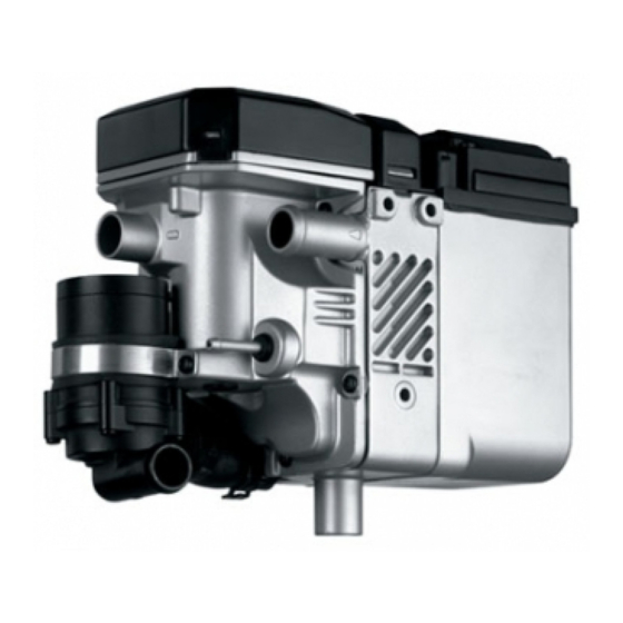
- Page 4 5. Coolant Inlet Connection Pipe 10. Heat Exchanger The Webasto TTC is designed for Class 3-7 vehicles. This dynamic system allows you to preheat engines on or offsite. The TTC offers high performance with low power and fuel consumption. Approximately 2-hours of operation eliminates overnight idling for heating and the need for expensive electrical plug-ins.
-
Page 5: Legal Provisions
Heater installation must be performed in accordance with the manufacturer`s installation instructions. Any deviation from these instructions are only permitted with the written approval from Webasto Thermosystems Inc. It is the dealer™ responsibility to approve installations not performed by Webasto trained personnel. - Page 6 Thermo Top C (TTC) Operating the Webasto Operating the Webasto Thermo Top C (TTC) Before switching on theTTC, set vehicle heating system to the fiheat position and open any shut off valves. Depending on the type of control installed in the dashboard of the vehicle, the TTC can be operated by the following methods.
-
Page 7: Operating The Heater
WARNING! Explosion hazard! The heater must be switched fiOFF while refueling and at fueling stations. WARNING! Explosion hazard! Do not operate any Webasto heater in an area where toxic or explosive materials or fumes may be present. Switching Off Manually: When heating is no longer required, switch the TTC heater off by means of the toggle switch or by pressing the fiinstan heatf button on the optional timer. - Page 8 Thermo Top C (TTC) Operating the Heater Preselected Starting Times The preselected starting time is the time at which the timer switches the heater on automatically. We recommend that memory locations 1 and 2 be used for presetting starting times within 24 hours of setting the timer.
- Page 9 Operating the Heater Thermo Top C (TTC) Digital Timer Setting / Operating Instructions Switching the heater Manually: by pressing the button (continuous heating mode) Automatically: by programming the heater starting time Switching the heater Manually: by pressing the button Automatically: after the programmed operating time has elapsed.
-
Page 10: Technical Data
The following data is subject to the normal tolerance for heaters, if no tolerance is specified. This is approximately +/-10% in an ambient of 20 °C at nominal voltage. Heater Thermo Top C (TTC) Diesel Design Coolant heater with evaporator burner (Ferro-Tech Technology) - Page 11 Technical Data Thermo Top C (TTC) Heater Dimensions Fig. 301: Heater Dimensions Fig. 302: Fuel Pump Dimensions...
-
Page 12: General Information
Thermo Top C (TTC) Installation Installation General Information Webasto will take you step by step through the installation process to ensure successful operation for years to come. The installation must be performed in accordance with the installation instructions provided in this manual. WARNING! Asphyxiation risk! The heater must not be installed in either the driver™s c ompartment or in the... - Page 13 Installation Thermo Top C (TTC) Mounting the Heater Fig. 402: Permissible Heater Installation Positions WARNING! Asphyxiation risk! DO NOT mount heater inside passenger, sleeper or storage areas. CAUTION! The openings of the water connecting pipes must never point in a downward direction in any installation position.
-
Page 14: Exhaust Pipe Connection
(i.e., brake lines, electrical wiring, hoses). NOTE: Additional flexible exhaust tubing is available from your Webasto Distributor or Dealer under part number 900126. One meter (39 inches) of flexible exhaust tubing has been supplied with the heater. Attach tube to the heater with exhaust clamp supplied. -
Page 15: Plumbing The System
Installation Thermo Top C (TTC) Plumbing the System 4.6.1 General Information The TTC with coolant circulating pump must be mounted at least 6" (15 cm) below the lowest permissible coolant level of the vehicles cooling system. Minimum amount of coolant in the cooling system should be at least 1.0 US gal. (4.0 l). Independent heating systems require a minimum of 3.0 US gal. - Page 16 Engine Block Preheating: 1. Remove radiator pressure cap and release system pressure. 2. Drain coolant from engine. 3. Plumb the Webasto system as shown above. 4. Refill engine coolant as per engine manufacturer™s r ecommendations and reinstall the radiator pressure cap.
- Page 17 Installation Thermo Top C (TTC)
- Page 18 Thermo Top C (TTC 4.6.3 Contents - Engine Connections Caterpillar 3116 ..........................408 3176 ..........................408 3306 ..........................409 3408 ..........................409 C-10/C-12 ........................410 Cummins B Series .......................... 411 C Series .......................... 412 Detroit Diesel Series 50......................... 413 Series 55......................... 413 Mack E6 / E7 ..........................
- Page 19 Thermo Top C(TTC) Caterpillar Caterpillar 3116 Caterpillar 3176...
- Page 20 Thermo Top C (T Caterpillar Caterpillar 3306 Caterpillar 3408...
- Page 21 Thermo Top C (TTC) Caterpillar Caterpillar C-10, C-12...
- Page 22 Thermo Top C (TTC) Cummins Cummins B Series...
- Page 23 Thermo Top C (TTC) Cummins Cummins C Series...
- Page 24 Thermo Top C (TTC) Detroit Diesel Detroit Diesel Series 50 Detroit Diesel Series 55...
- Page 25 Thermo Top C (TTC) Mack Mack E6 / E7...
-
Page 26: Fuel System
Thermo Top C (TTC) Installation Installation Fuel System 4.7.1 General Description The pump, fuel line and fuel standpipe are integral to the systems reliability and must be installed according to these instructions to ensure proper heater operation. 4.7.2 Fuel System Limitations CAUTION! If the fuel tank is higher than the fuel pump, the top of the tank may not be more than 20"... - Page 27 Installation Thermo Top C (TTC) 4.7.3 Fuel Pump The fuel pump MUST be mounted in a horizontal position in order to function correctly and deliver the proper quantity of fuel. Mount the fuel pump as close to the fuel source as practicable.
- Page 28 Thermo Top C (TTC) Installation Fuel Standpipe Fig. 406: Fuel Standpipe...
- Page 29 Installation Thermo Top C (TTC) 4.7.5 Fuel Line Fuel line, couplers and clamps are provided in the installation kit and are required for proper operation. CAUTION! Fuel line must be secured every 12f (30 cm) and kept away from hot exhaust and moving parts (drive shaft, wheels, etc.
-
Page 30: Wiring Connections
Power Connection to Battery Power harness connection instructions: 1. Route and secure wire harness from Webasto heater to battery box and cut harness to length. 2. Strip wires and crimp supplied ring tongue terminals to the positive (red) and negative (brown) wire leads. - Page 31 Installation Thermo Top C (TTC) Timer installation instructions: 1. Select a suitable location in the vehicle dash for the timer. 2. Temporarily affix timer drilling template to dash or see timer dimensions. 3. Cutout hole to dimensions on template or timer dimensions.
- Page 32 Thermo Top C (TTC) Installation 4.8.4 Wiring Diagram - Thermo Top C TTC) (12 Volt) with On/Off Toggle Switch Fig. 410: Wiring Diagram - Thermo Top C (TTC) with On/Off Toggle Switch...
- Page 33 Installation Thermo Top C (TTC) 4.8.5 Wiring Diagram - Thermo Top C (TTC) (12 Volt) with Optional Digital Timer Fig. 411: Wiring Diagram - Thermo Top C (TTC) with Optional Digital Timer...
-
Page 34: Initial Operation
6. Shut off the engine. 7. Switch on Webasto heater using the toggle switch or the fiInstan Heatf button on timer and check: Switch toggle or instant heat button illuminates. - Page 35 10. Switch OFF TTC heater. 11. Re-tighten hose clamps to 45 in/LB. (5 Nm) and inspect installation for leaks. 12. Complete the warranty card and send to Webasto Thermosystems. NOTE: Necessary information to complete warranty card and ensure full warranty coverage can be found...
-
Page 36: Maintenance Of The Heater
The following maintenance procedures should be performed annually before each heating season: NOTE For major repair and spare parts, return to your authorized Webasto Thermosystems Specialist. Enclosure Box and Heater - Clean the heater and enclosure box from any accumulated debris or dust with compressed air. - Page 37 Maintenance of the Heater Thermo Top C (TTC)
-
Page 38: Basic Troubleshooting
Thermo Top C (TTC) Basic Troubleshooting Basic Troubleshooting General Information This section describes troubleshooting procedures for the TTC coolant heater. Troubleshooting is normally limited to the isolation of defective components. CAUTION Troubleshooting requires profound knowledge about structure and theory of operation of the heater components and may only be performed by skilled personnel. - Page 39 The lockout mode should now be canceled and the heater operating normally. PC Diagnostics Kit CAUTION Diagnostics equipment is intended for use by Webasto trained personnel at authorized Webasto Distributor, Dealer and End User service facilities. It is possible to read and remove (reset) stored fault codes from the TTC memory.
Need help?
Do you have a question about the Thermo Top C and is the answer not in the manual?
Questions and answers