Table of Contents
Advertisement
Quick Links
Advertisement
Table of Contents

Subscribe to Our Youtube Channel
Related Manuals for Rosen Aviation 1500


Summary of Contents for Rosen Aviation 1500
-
Page 2: Table Of Contents
Table of Contents Introduction and Monitor Overview ....1 Monitor Diagram ..........2 Pinouts ..............3 Main Interface Signal ............3 External Control Interface ..........6 RGB or Composite Video Option Selection ...... 7 Installation Instructions ........8 Operation ............10 Power Status LED ............ - Page 3 1020 Owen Loop South Eugene OR 97402 541-342-3802 www.rosenaviation.com Doc # 9000782 Rev. C *9000782*...
-
Page 4: Introduction And Monitor Overview
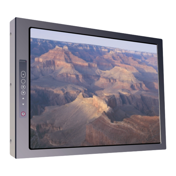
Introduction and Monitor Overview Introduction and Monitor Overview Welcome to the 1500 Series Technical Manual. This manual provides an overview of monitor details including: • Pinouts • Installation • Operation • Troubleshooting • Specifications The 1500 series monitor includes the following features: •... -
Page 5: Monitor Diagram
Monitor Diagram Monitor Diagram Outline Dimensions (Inches) Front... -
Page 6: Pinouts
Pinouts Pinouts Pinout Document Number 9000493 Main Interface Signal The input connector on this monitor is a 21W4 Male Combo D-subminiature with 17 Size 20 contacts (standard density D-sub) and four Size 8 coaxial contacts, mounting in a Size 4 D-subminiature shell. Recommended mating connector: ITT Cannon P/N DCA21WA4SA197FO Note: Backshell of main connector is chassis ground. - Page 7 Pinouts Monitor Signal A1 Center - Signal Red A1 Shield - Shield Red return A2 Center - Signal Green A2 Shield - Shield Green return A3 Center - Signal Blue A3 Shield - Shield Blue return A4 Center - Signal Composite video A4 Shield - Shield Composite video return Description of Operation Signal...
- Page 8 Pinouts Red graphics input, 1 Vpp, A1 Signal/Shield Input 75 ohm Green graphics input, 1 Vpp, A2 Signal/Shield Input 75 ohm Blue graphics input, 1 Vpp, A3 Signal/Shield Input 75 ohm Composite video Input A4 Signal/Shield input, 1 Vpp, 75 ohm...
-
Page 9: External Control Interface
Pinouts External Control Interface (P/N 0300-402) The external VIP control interface is a 9-pin standard density D-subminiature male connector. Control Signal Power On/Off Source Select Down Menu/Select Left Right Ground (Switch Common) -
Page 10: Rgb Or Composite Video Option Selection
Pinouts Dip Switch option selection Using DIP switches located near the input connectors. . Operation is as follows: Function Constant Ground Switching. Monitor displays RGB when pin 6 of the main interface connector is held to ground. Monitor displays Composite video when pin 6 of main interface connector is held High (5 V max.).Front panel source... -
Page 11: Installation Instructions
Installation Instructions Installation Instructions The monitor can be mounted from any combination of two sides. (Dimensions In Inches) MONITOR TOP FRONT MONITOR BOTTOM FRONT 11x #10-32 unc-2B Mounting Holes MONITOR SIDES... -
Page 12: Monitor Rear
Installation Instructions MONITOR REAR Warning! Maximum screw penetration depth: Bottom: 0.39 inches Sides: 0.39 inches Rear: 0.39 inches The top, bottom, rear, and both sides of the monitor include mounting holes for #10-32 mounting screws. Note: Each mounting hole includes a 10-32 flathead screw. To install the monitor, remove only the screws that will be used to install the monitor. -
Page 13: Operation
Operation Operation Power Status LED The front switch panel includes a power status LED. LED StatusDescription Green Monitor is on. Monitor is in Standby mode. Front Switch Panel Features To operate the 15" LCD monitor, use the front switch panel buttons shown below. -
Page 14: On Screen Display (Osd) Main Menu
Operation On Screen Display (OSD) Main Menu The On Screen Display (OSD) provides a set of menus that enable you to adjust or view monitor features. Main menu selections lead to submenus with additional choices. Press the Menu button on the switch panel to see the Main menu. Menu Option Description Source... -
Page 15: Display Submenu
Operation Display Submenu Choose “ from the Main menu to adjust monitor Display” features, described below. Menu Option Description Brightness 100-step brightness control. Contrast 100-step contrast control. Saturation Composite video only. Adjust color tone. Composite video only. Adjust color tint. Scaling/Position &... - Page 16 Operation Picture in Picture Control Submenu Choose “ from the Main menu only when Analog PIP Control” RGB video is selected to see the PIP submenu, described below. Menu Option Description PIP Size Select small, medium, or large to turn on PIP and select a window size.
-
Page 17: Troubleshooting
Troubleshooting Troubleshooting If the monitor does not function properly, refer to the following troubleshooting table for symptoms and possible solutions before contacting Rosen field support. Note: Always use an oscilloscope to verify the video signal. Always use a multimeter to verify voltages. Check actual results against the requirements described in this manual. - Page 18 Troubleshooting Problem Possible Solutions Image flickers • Verify that the signal cable is secure. • Verify that the vertical frame frequency is 75 Hz or less. If using the monitor with a PC in Windows, change the Display Control Panel to 60 Hz to achieve the best performance.
-
Page 19: Specifications
Specifications Specifications LCD Performance Screen Resolution (pixels) 1024 w x 768 h Display Viewing Area 12.2 x 9.2 inches Viewing Angle Horizontal ±80º Vertical ±80º Contrast Ratio 400:1 Backlight Lamp Life (hours) 50,000 Screen Brightness 200 Nits (Minimum) 250 Nits (Typical) Mechanical Packaging Weight 6.1 lbs.(max) ±5%... -
Page 20: 15" Monitor Do-160D Test Matrix
15” Monitor DO-160D Test Matrix Section Description Category Temp & Alt Temp Variation Humidity Op Shock & Crash Safety Vibration Explosion Proofness Waterproofness Fluids Susceptibility Sand & Dust Fungus Resistance Salt Spray Magnetic Effect Power Input Voltage Spike AF Cond Suscept – Pwr Induced Signal Suscept RF Suscept (Cond&Rad) Emission of RF Energy... -
Page 21: Disclaimer
Disclaimer All information, including illustrations, is believed to be reliable. Users and/ or installers, however, should independently evaluate the suitability of each product for their application. Rosen makes no warranties as to the accuracy or completeness of the information, and disclaims any liability regarding its use or installation.
Need help?
Do you have a question about the 1500 and is the answer not in the manual?
Questions and answers