Table of Contents
Advertisement
Quick Links
OEM SALES
CORPORATE OFFICE
www.
8 Shackleford Plaza,
1020 Owen Loop South
Suite 201
Eugene, OR 97402
rosenaviation
Little Rock, AR 72211
1-888-668-4955
.com
1-888-523-7523
Fax (541) 342-4912
Fax (501) 225-1015
Document # 9002428 Rev B
DEALER & OPERATOR SALES
1121 Warren Ave, Suite 240
Downers Grove, IL 60515
1-800-859-5058
Fax (630) 963-4405
9002428
17
DISPLAY
DISPLAY
1700
Compliant to DO-160D
SlimLine
Model Number
1700
www.
rosenaviation
.com
Advertisement
Table of Contents

Subscribe to Our Youtube Channel
Related Manuals for Rosen Aviation SlimLine 1700


Summary of Contents for Rosen Aviation SlimLine 1700
- Page 1 SlimLine Model Number 1700 DISPLAY DISPLAY 1700 OEM SALES CORPORATE OFFICE DEALER & OPERATOR SALES www. www. 8 Shackleford Plaza, 1121 Warren Ave, Suite 240 1020 Owen Loop South Suite 201 Eugene, OR 97402 Downers Grove, IL 60515 rosenaviation rosenaviation Little Rock, AR 72211 1-800-859-5058 1-888-668-4955...
-
Page 2: Table Of Contents
Table of Contents Introduction and Display Overview ....3 Display Diagram ..........4 Pinouts ..............5 Main Interface Signal ............ 5 External Control Interface ..........8 DIP Switch Option Selection ........9 Installation Guidelines........12 Operation ............14 Power Status LED ............14 Front Switch Panel Features ........ - Page 3 1020 Owen Loop South Eugene OR 97402 541-342-3802 www.rosenaviation.com...
-
Page 4: Introduction And Display Overview
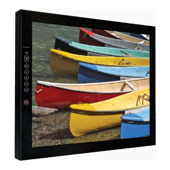
Introduction and Display Overview Introduction and Display Overview Welcome to the 1700 Technical Manual for the 17" SlimLine LCD Display. This manual provides an overview of display details including: • Pinouts • Installation • Operation • Troubleshooting • Specifications The 1700 model includes the following features: •... -
Page 5: Display Diagram
Display Diagram Display Diagram Outline Dimensions (inches) 15.32" 13.38" .88" 10.17" 17.0" 12.72" 1.04" 1.12" 10-32 MOUNTING HOLES (3X EACH SIDE) 4.50" FRONT 4.50" 1 .86" Page 4 Rosen Aviation Displays... -
Page 6: Pinouts
Pinouts Pinouts Main Interface Signal The input connector on this monitor is a 21W4 Male Combo D-subminiature with 17 size 20 contacts (standard density D- sub) and four Size 8 coaxial contacts, mounting in a size 4 D- subminiature shell. Recommended mating connector: ITT Cannon: P/N DCA21WA4SA197FO. - Page 7 Display Signal Reserved Digital GND (RGB video select return) Digital GND Digital GND Signal Red Shield Red Return Signal Green Shield Green Return Signal Blue Shield Blue Return Signal Composite Video Shield Composite Video Return Page 6 Rosen Aviation Displays...
- Page 8 Pinouts Description of Operation Aircraft power supply Input +28V, 28V Return Output IR +5V, IR GND Power for optional External IR receiver IR receiver signal Input IR Signal input RGB/Video TTL level input. Used to select Input Select Switch which input (RGB or Composite) is displayed.
-
Page 9: External Control Interface
The external VIP control interface is a 9-pin standard density D-subminiature male connector. Each function can be activated by a momentary connection to ground. Control Signal Power On/Off Source Select Down Menu/Select Left Right Ground (Switch Common) Page 8 Rosen Aviation Displays... -
Page 10: Dip Switch Option Selection
Dip Switch Option Selection Dip Switch Option Selection Using DIP switches located near the input connectors. Operation is as follows: Function Constant Ground Switching See pg 10 for description Momentary Ground Switching See pg 10 for description Autodetect. See pg 10 for description Manual Mode See pg 11 for description Monitor defaults to Off... - Page 11 Composite Video input, whether a signal is present or not. The Source button located on the front panel membrane switch and optional external switch controller can also be used to switch back and forth between the RGB and Composite Video inputs. Page 10 Rosen Aviation Displays...
- Page 12 Dip Switch Option Selection (cont) Manual Mode This mode will not switch between RGB and Composite Video through the Auto-Detect, Constant Ground or Momentary Ground options. The Source button located on the front panel membrane switch and optional external switch controller can be used to switch back and forth between the RGB and Composite Video inputs.
-
Page 13: Installation Guidelines
Installation Guidelines Installation Guidelines The monitor can be mounted from any combination of two sides. ( Dimensions in inches) FRONT Display Top Display Bottom FRONT Display Sides Page 12 Rosen Aviation Displays... -
Page 14: Monitor Rear
Installation Guidlines MONITOR REAR Warning! Maximum screw depth: .75 inches Bottom .75 inches Sides .75 inches Rear .50 inches Cooling and Ventilation The monitor is cooled by the flow of air, or natural convection. Special care must be taken with the installation to provide a proper environment for air flow. -
Page 15: Operation
Analog RGB and Composite video. Note: Only functions when DIP switch is set to Momentary Ground or Manual mode. Press to select a menu option, or to increase or decrease a value. Power Press to power the monitor on or off. Page 14 Rosen Aviation Displays... -
Page 16: On Screen Display (Osd) Main Menu
Operation On Screen Display (OSD) Main Menu The On Screen Display (OSD) provides a set of menus that enable you to adjust or view monitor features. Main menu selections lead to submenus with additional choices. Press the menu button on the switch panel to see the main menu. Main Menu Submenus To switch to different main menus (osd, utility, auto) use... -
Page 17: Picture Submenu
RGB Mode. OSD Submenu Menu Option Description H Position OSD Horizontal Position V Position OSD Vertical Position OSD Time Out Time in which OSD turns off if left alone Return Returns You to Main Menu Page 16 Rosen Aviation Displays... - Page 18 Operation Utility Submenu Menu Option Description Freeze Frame Freezes Picture Frame Reset Factory Reset to Default Settings Color Temperature Color Adjustment in RGB Mode Only Information Monitor Info Return Returns You to Main Menu Auto Submenu Menu Option Description Auto Automatically adjusts image size in RGB mode Exit Submenu...
-
Page 19: Troubleshooting
• Verify that the pinout is correct. • Verify that the video source is on and has a tape or DVD installed. Color is Out of • Refer to the Main menu features on page 15. Adjustment Page 18 Rosen Aviation Displays... -
Page 20: Technical Support
The LCD should be cleaned with a lens grade tissue for cleaning optical surfaces and isopropyl alcohol. Technical Support For technical support or to order parts, contact Rosen Aviation Displays at: 888-668-4955 or visit us at: www.rosenaviation.com 17” SlimLine LCD Page 19... -
Page 21: Specifications
7.9 lbs ± 5% Power Requirements 28VDC 40W max. Video Performance Video Standards NTSC, PAL, SECAM, RS-170 Graphics Standards VGA, SVGA, XGA, SXGA (75 Hz max) Video input 1V peak-to-peak, 75 Ohms Operating Temperature 0ºC - 50ºC Warranty Page 20 Rosen Aviation Displays... -
Page 22: 17" Monitor Do-160D Test Matrix
Disclaimer 17” Monitor DO-160D Test Matrix Section Description Category Temp & Alt Temp Variation Humidity Op Shock & Crash Safety Vibration Explosion Proofness Waterproofness Fluids Susceptibility Sand & Dust Fungus Resistance Salt Spray Magnetic Effect Power Input Voltage Spike AF Cond Suscept – Pwr Induced Signal Suscept RF Suscept (Cond&Rad) Emission of RF Energy... -
Page 23: Disclaimer
Specifications are subject to change without notice. Rosen reserves the right to make changes - without notification to buyer - to materials or processing that do not affect compliance with any applicable specifications. Page 22 Rosen Aviation Displays...
Need help?
Do you have a question about the SlimLine 1700 and is the answer not in the manual?
Questions and answers