Table of Contents
Advertisement
Quick Links
Download this manual
See also:
Technical Manual
Advertisement
Table of Contents

Related Manuals for Rosen Aviation 1700


Summary of Contents for Rosen Aviation 1700
- Page 1 1700 1700...
-
Page 2: Table Of Contents
Table of Contents Introduction and Monitor Overview ....3 Monitor Diagram ..........4 Pinouts ..............5 Main Interface Signal ............5 External Control Interface ..........8 RGB or Composite Video Option Selection ...... 9 Installation Instructions ........10 Operation ............12 Power Status LED ............ - Page 3 1020 Owen Loop South Eugene OR 97402 541-342-3802 www.rosenaviation.com Doc # 9000677 Rev. C *9000677*...
-
Page 4: Introduction And Monitor Overview
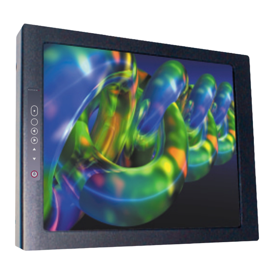
Introduction and Monitor Overview Introduction and Monitor Overview Welcome to the 1700 Technical Manual for the 17" Slimline LCD monitor. This manual provides an overview of monitor details including: • Pinouts • Installation • Operation • Troubleshooting • Specifications The 1700 base model includes the following features: •... -
Page 5: Monitor Diagram
Monitor Diagram Monitor Diagram Outline Dimensions FRONT Rosen Aviation Displays Page 4... -
Page 6: Pinouts
Pinouts Pinouts Pinout Document Number 9000493 Main Interface Signal The input connector on this monitor is a 21W4 Male Combo D-subminiature with 17 Size 20 contacts (standard density D-sub) and four Size 8 coaxial contacts, mounting in a Size 4 D-subminiature shell. Recommended mating connector: ITT Cannon: P/N DCA21WA4SA197FO. - Page 7 RGB graphics input, TTL level Hsync, Input 470 ohm termination Vsync Reference ground for RGB sync Computer sync GND Input Digital GND, pins 15, Common digital ground Input 16, 17 connection, connected to Computer sync GND Rosen Aviation Displays Page 6...
- Page 8 Pinouts Signal Input/Output Description Red graphics input, 1 Vpp, Input A1 signal/shield 75 ohm Green graphics input, 1 Vpp, A2 signal/shield Input 75 ohm Blue graphics input, 1 Vpp, A3 signal/shield Input 75 ohm Composite video A4 signal/shield Input input, 1 Vpp, 75 ohm 17”...
-
Page 9: External Control Interface
Pinouts External Control Interface (0300-402) The external VIP control interface is a 9-pin standard density D-subminiature male connector. Control Signal Power On/Off Source Select Down Menu/Select Left Right Ground (Switch Common) Rosen Aviation Displays Page 8... -
Page 10: Rgb Or Composite Video Option Selection
Pinouts RGB or Composite Video Option Selection The monitor can be configured to switch between RGB or Composite video using DIP switches located near the input connectors. The DIP switch selection is detected only at power on. Operation is as follows: Function Constant Ground Switching. -
Page 11: Installation Instructions
Installation Instructions Installation Instructions The monitor can be mounted from any combination of two sides. FRONT MONITOR TOP MONITOR BOTTOM FRONT MONITOR SIDES Rosen Aviation Displays Page 10... -
Page 12: Monitor Rear
Installation Instructions MONITOR REAR Warning! Maximum screw penetration depth: .75 inches Bottom .75 inches Sides .75 inches Rear .50 inches Natural Convection Installation here are three display venting configurations recommended for a natural convection installation: Option A = Top and Bottom, or Option B = Top and Rear, or Option C = Top, Bottom, and Rear Design considerations:... -
Page 13: Operation
Analog RGB and Composite video. Note: Only functions when DIP switch is set to Momentary Ground. Press to select a menu option, or to increase or decrease a value. Power Press to power the monitor on or off. Rosen Aviation Displays Page 12... -
Page 14: On Screen Display (Osd) Main Menu
Operation On Screen Display (OSD) Main Menu The On Screen Display (OSD) provides a set of menus that enable you to adjust or view monitor features. Main menu selections lead to submenus with additional choices. Press the Menu button on the switch panel to see the Main menu. Menu option Description Source... -
Page 15: Display Submenu
Main menu to see the submenu, (Analog RGB) described below. Menu option Description Position Analog RGB only. Press to move the display image. Fill Screen Maximize the image size. Fill to Aspect Ratio Adjust image aspect ratio to 4:3. Rosen Aviation Displays Page 14... -
Page 16: Picture In Picture Control Submenu
Operation Picture in Picture Control Submenu Choose “ from the Main menu only when Analog PIP Control” RGB video is selected to see the PIP submenu, described below. Menu option Description PIP Size Select small, medium, or large to turn on PIP and select a window size. -
Page 17: Troubleshooting
• Verify that the pinout is correct. • Verify that the video source is on and has a tape or DVD installed. Color is out of Refer to the Main menu features on page 11. adjustment Rosen Aviation Displays Page 16... - Page 18 Troubleshooting Problem Possible Solutions Image flickers • Verify that the signal cable is secure. • Verify that the vertical frame frequency is 75 Hz or less. If using the monitor with a PC in Windows, change the Display Control Panel to 60 Hz to achieve the best performance.
-
Page 19: Specifications
8 lbs ± 5% Power Requirements 28VDC 40W max. Video Performance Video Standards NTSC, PAL, SECAM Graphics Standards VGA, SVGA, XGA, SXGA (75 Hz max) Video input 1V peak-to-peak, 75 Ohms Operating Temperature 0ºC - 50ºC Warranty Rosen Aviation Displays Page 18... -
Page 20: 17" Monitor Do-160D Test Matrix
Disclaimer 17” Monitor DO-160D Test Matrix Section Description Category Temp & Alt Temp variation Humidity Op shock & crash safety Vibration Explosion Proofness Waterproofness Fluids Susceptibility Sand & Dust Fungus Resistance Salt Spray Magnetic Effect Power Input Voltage Spike AF Cond Suscept – Pwr Induced Signal Suscept RF Suscept (Cond&Rad) Emission of RF Energy... -
Page 21: Disclaimer
Specifications are subject to change without notice. Rosen reserves the right to make changes - without notification to buyer - to materials or processing that do not affect compliance with any applicable specifications. Rosen Aviation Displays Page 20...
Need help?
Do you have a question about the 1700 and is the answer not in the manual?
Questions and answers