Table of Contents
Advertisement
Quick Links
Advertisement
Table of Contents

Related Manuals for Brymen BM157


Summary of Contents for Brymen BM157
- Page 1 USER'S MANUAL BM157 & BM357 3-Phase PowerClamp...
- Page 2 1) SAFETY This manual contains information and warnings that must be followed for operating the instrument safely and maintaining the instrument in a safe operating condition. If the instrument is used in a manner not specified by the manufacturer, the protection provided by the instrument may be impaired.
- Page 3 WARNING To reduce the risk of fire or electric shock, do not expose this product to rain or moisture. The meter is intended only for indoor use. To avoid electrical shock hazard, observe the proper safety precautions when working with voltages above 60 VDC or 30 VAC rms. These voltage levels pose a potential shock hazard to the user.
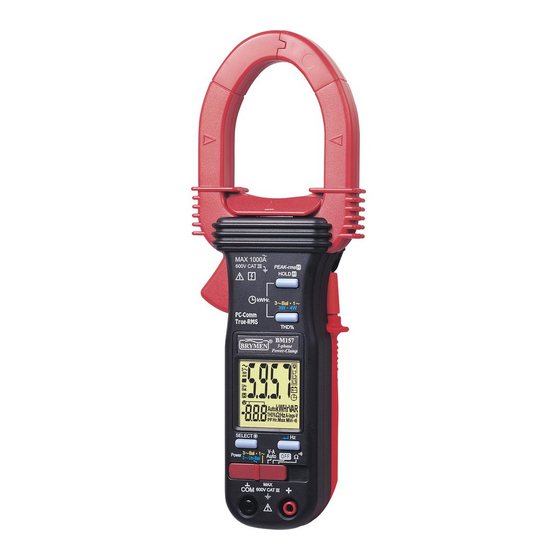
- Page 4 3) PRODUCT DESCRIPTION Note: Top of the line model is used as representative for illustration purposes. Please refer to your respective model for function availability. 1) Transformer Clamp Jaws for AC current magnetic field pick up 2) Jaw marking lines for ACA (& thus Power) position error indication 3) Hand/Finger Barrier to indicate the limits of safe access to the jaws during...
- Page 5 4) OPERATION CAUTION Before and after hazardous voltage measurements, test the voltage function on a known source such as line voltage to determine proper meter functioning. AutoVA function Set the slide-switch function-selector to the position. ●With no input, the meter displays “ ”...
- Page 6 CAUTION (Application and removal of the Clamp-on meter) ●For non-invasive ACA current measurements, press the jaw trigger and clamp the jaws around only one single conductor of a circuit for load current measurement. Make sure the jaws are completely closed, or else it will introduce measurement errors. Enclosing more than one conductor of a circuit will result in differential current (like identifying leakage current) measurement.
- Page 7 Peak-rms mode Peak-rms compares and displays the maximum RMS value of surge voltage or current with durations as short as 65ms. When ACV or ACA function is auto-selected or manual-selected, press and hold Peak-rms button for one second or more toggles to this mode.
- Page 8 HOLD mode When any function is auto-selected or manual-selected, press HOLD button momentarily toggles to Hold mode. The annunciator “ ” turns on. Hold mode freezes the display for later viewing. Notes on Displacement Power Factor & Total Power Factor ●Introduction: Power is the rate of change of energy with respect to time (in terms of voltage V and current A).
- Page 9 Single-Phase Power & 3-Phase Balanced-Load Power functions 1~” Power position. Set the slide-switch function-selector to the “3~Bal ● ●Default at last selected function. ●Press “3~Bal 1~” button momentarily to toggle between “Single-Phase” and ● “3-Phase Balanced Load” Power functions. Annunciators “ ”...
- Page 10 1. PF (Total Power Factor) is displayed automatically in the secondary mini display. 2. Annunciator “A-lags-V” turns on to indicate an inductive circuit is being measured. That is, the Current waveform is lagging the Voltage waveform, and the phase-shift angle θ is “+”. 3.
- Page 11 kWHr (kilo-Watt-Hour) Recording function 1~” Power position. Setup power Set the slide-switch function-selector to the “3~Bal ● measurements as mentioned in the previous “Single-Phase Power & 3-Phase Balanced-Load Power functions” section ●To start ( ) kWHr Recording, press “3~Bal 1~” and “HOLD” buttons at the “...
- Page 12 ●To stop ( 1~” and “HOLD” buttons at the same time again. “ ” ), press the “3~Bal ● Annunciator “ ” turns off. The kWHr Recording result is then displayed on the LCD for immediate viewing. Annunciator “ ” turns on & flashes. ) kWHr ●When the low battery annunciator “...
- Page 13 ●When the reading is stable, press “ ” button momentarily to enter the second measuring value. The meter will then calculate, store and display the total 3-Phase L1 L2 L3” turn on. Power result automatically. Annunciators “ ●Press “ ” button momentarily again for new measurements. ●Press “SELECT”...
- Page 14 ●When the reading is stable, press “ ” button momentarily to enter the second measuring value. L3”, and ●Then clamp the jaws around “Line 3” as reminded by annunciators “ connect Black test probe (COM terminal) to “Line n (neutral)” and Red test probe (+ terminal) to “Line 3”...
- Page 15 functions / Set the slide-switch function-selector to the / function position. Default at last selected function. Press SELECT button to toggle between and measurement functions. Backlighted display Press the SELECT button for 1 second or more to toggle the display backlight on or off. Auto Power Off (APO) The meter turns off after approximately 30 minutes of neither switch nor button activity.
- Page 16 Line Frequency setup Press-and-hold the Hz button while powering the meter on. LCD displays the last 50Hz or 60 Hz setup. Press SELECT button momentarily to select 50Hz or 60Hz to cope with your local line frequency. Press Hz button for one second to store your selection and resume measurements.
- Page 17 Battery replacement The meter uses standard 1.5V AAA Size (NEDA 24A or IEC LR03) battery X 2 Loosen the 2 captive screws from the battery cover case. Lift the battery cover case. Replace the batteries. Replace battery cover case. Re-fasten the screws. 6) Specifications General Specifications Display :...
- Page 18 Temperature Coefficient : nominal 0.15 x (specified accuracy)/ C @(0 C -18 C or C -40 C), or otherwise specified Sensing : True RMS sensing Safety : Meets IEC61010-1 2nd Ed., EN61010-1 2nd Ed., UL61010-1 2nd Ed., CAN/CSA C22.2 No. 61010.1-0.92, IEC61010-2-032, EN61010-2-032 & UL61010B-2-032 Measurement Category : III 600 Volts ac &...
- Page 19 Electrical Specifications Accuracy is ±(% reading digits + number of digits) or otherwise specified, at 23 C ±5 C & less than 75% R.H. True RMS ACV & ACA clamp-on accuracies are specified from 0% to 100% of range or otherwise specified.
- Page 20 ACA Current (Clamp-on) RANGE Accuracy 1) 2) 50Hz / 60Hz 40.00A, 400.0A, 1.0% + 5d 1000A (600A for model 357) 45Hz ~500Hz 40.00A, 400.0A 2.0% + 5d 1000A (600A for model 357) 2.5% + 5d 500Hz ~ 3.1kHz 40.00A, 400.0A 2.5% + 5d 1000A (600A for model 357) 3.0% + 5d...
- Page 21 THD%-F (model 157 only) RANGE Accuracy Harmonic order Fundamental 1.5% + 6d 2nd ~ 3rd 7% + 6d 0.0% ~50.0% 4th ~ 21st 2.5% + 6d 2) 3) 22nd ~ 51st 10% + 10d 2nd ~ 3rd Unspecified 50.0% ~100% 5) 6) 4th ~ 21st 2.5% + 6d...
- Page 22 Ohms RANGE Accuracy 1.0% + 6d 999.9 Open Circuit Voltage : 0.4VDC typical Audible Continuity Tester Audible threshold: between 10 and 300. Response time: 250s Single-Phase & 3-Phase Balanced-Load Power RANGE Accuracy 1) 2) 3) 0 ~ 600.0kVA F ~ 10th 11th ~ 45th 46th ~ 51st @ PF = 0.99 ~ 0.1...
- Page 23 Total Power Factor (PF) RANGE Accuracy F ~ 21st 22nd ~ 51st 0.10 ~ 0.99 Specified accuracy @ ACA fundamental > 2A ; ACV fundamental > 50V A-lags-V Indication: LCD annunciator “A-lags-V” turns on to indicate an inductive circuit, or Current A lags Voltage V (i.e., phase-shift angleθ...
- Page 24 BRYMEN's warranty does not apply to accessories, fuses, fusible resistors, spark gaps, batteries or any product which, in BRYMEN's opinion, has been misused, altered, neglected, or damaged by accident or abnormal conditions of operation or handling.
Need help?
Do you have a question about the BM157 and is the answer not in the manual?
Questions and answers