
Subscribe to Our Youtube Channel
Related Manuals for Brymen BM110M


Summary of Contents for Brymen BM110M
- Page 1 USER'S MANUAL BM110M, BM111M, BM112M Single Display BM127M, BM128M Twin Displays Versatile Clamp-on Multimeter Series...
-
Page 2: Terms In This Manual
1) SAFETY This manual contains information and warnings that must be followed for operating the instrument safely and maintaining the instrument in a safe operating condition. If the instrument is used in a manner not specified by the manufacturer, the protection provided by the instrument may be impaired. -
Page 3: International Electrical Symbols
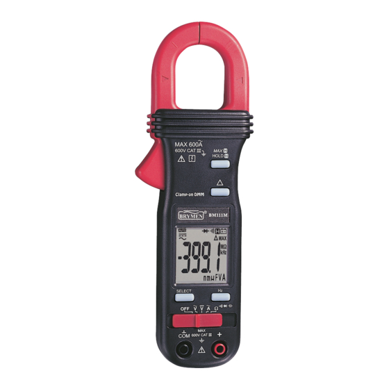
WARNING To reduce the risk of fire or electric shock, do not expose this product to rain or moisture. The meter is intended only for indoor use. To avoid electrical shock hazard, observe the proper safety precautions when working with voltages above 60 VDC or 30 VAC rms. These voltage levels pose a potential shock hazard to the user. - Page 4 1) Transformer Clamp Jaw for AC current magnetic field pick up 2) Hand/Finger Barrier to indicate the limits of safe access of the meter during measurement 3) Push-buttons for special functions & features. Also as power ON/OFF buttons for ACA function in Twin Display Models 4) Push-buttons for special functions &...
-
Page 5: Operation
4) OPERATION CAUTION: Before and after hazardous voltage measurements, test the voltage function on a known source such as line voltage to determine proper meter functioning. DC Voltage, AC Voltage, Hz Frequency functions Set slide-switch to Voltage function position(s). Inputs are made through the test leads terminals. - Page 6 Note: The Hz trigger level is determined by the selected function-range from where the Hz function is activated. In ACV function: Activating the Hz function during significant measurements can get the most appropriate trigger level to avoid electrical noises in most cases. Electrical noise may cause unstable Hz reading.
- Page 7 Ω Ω Ω Ω Resistance, and Continuity functions Inputs are made through the test leads terminals. Slide-switch on defaults at Ω. Press SELECT button momentarily to select Continuity function which is convenient for checking wiring connections and operation of switches. A continuous beep tone indicates a complete wire.
- Page 8 CAUTION (Application and removal of the Clamp-on meter) For non-invasive ACA current measurements, press the jaw trigger and clamp the jaws around only one single conductor of a circuit for load current measurement. Make sure the jaws are completely closed, or else it will introduce measurement errors. Enclosing more than one conductor of a circuit will result in differential current (like identifying leakage current) measurement.
- Page 9 Temperature function (Twin Display Models only) Be sure to insert the banana plug type-K temperature bead probe Bkp60 with correct polarities. Slide-switch on defaults at degree C (Celsius). Press SELECT button momentarily to select degree F (Fahrenheit). You can also use a plug adapter Bkb32 (Optional purchase) with banana pins to type-K socket to adapt other type-K standard mini plug temperature probes.
- Page 10 applications. Flame signal current check should indicate steady flame signal of at least 2µA for a rectification type, or 1.5µA for an ultraviolet type (8µA for self checking systems). If a flame signal current with inadequate strength or fluctuation beyond 10%, check the following to avoid the risk of unwanted flame relay dropout : 1-1) For gas or oil flames (Minipeeper): Low supply voltage...
-
Page 11: Maintenance Warning
Relative zero mode (Single Display Models only) Relative zero mode allows the user to offset the meter consecutive measurements with the displaying reading as the reference value. The display will now show readings relative to the stored reference value. That is, display = reading - stored value. Press button momentarily toggles to relative zero mode. - Page 12 Cleaning and Storage Periodically wipe the case with a damp cloth and mild detergent; do not use abrasives or solvents. If the meter is not to be used for periods of longer than 60 days, remove the batteries and store them separately. Battery replacement The meters use standard 3V IEC-CR2032 coin batteries In Signle Display Models: One battery is used.
- Page 13 Storage Temperature : -20 C to 60 C, < 80% R.H. (with battery removed) Temperature Coefficient : nominal 0.15 x (specified accuracy)/ C @(0 C ~ 18 C or C ~ 40 C), or otherwise specified Sensing : Average sensing for Models 110M, 111M & 127M; True RMS for Models 112M &...
-
Page 14: Electrical Specification
Special Features : 30ms Max Hold (except Model 110M); Data Hold; Relative Zero mode (Models 110M, 111M & 112M only); Simultaneous A+V, A+Ω, A+ C (Models 127M & 128M only); Slim jaws; Light Weight ELECTRICAL SPECIFICATION Accuracy is ±(% reading digits + number of digits) or otherwise specified, at 23 C ±5 &... - Page 15 Ohms Capacitance* 2) 3) RANGE Accuracy RANGE Accuracy 0.8% + 8d 3.5% + 6d 400.0Ω 500.0nF, 5.000µF, 0.6% + 4d 50.00µF, 500.0µF, 4.000kΩ, 40.00kΩ, 3000µF 400.0kΩ 1.0% + 4d *Not available to Model 110M 4.000MΩ Additional 50.00nF range accuracy is 2.0% + 4d 40.00MΩ...
-
Page 16: Limited Warranty
BRYMEN's warranty does not apply to accessories, fuses, fusible resistors, spark gaps, batteries or any product which, in BRYMEN's opinion, has been misused, altered, neglected, or damaged by accident or abnormal conditions of operation or handling.
Need help?
Do you have a question about the BM110M and is the answer not in the manual?
Questions and answers