Sign In
Upload
Download
Add to my manuals
Delete from my manuals
Share
URL of this page:
HTML Link:
Bookmark this page
Add
Manual will be automatically added to "My Manuals"
Print this page
×
Bookmark added
×
Added to my manuals
Manuals
Brands
Brymen Manuals
Multimeter
BM789
User manual
Brymen BM789 User Manual
Hide thumbs
Also See for BM789
:
User manual
(37 pages)
1
2
3
4
5
6
7
8
9
10
11
12
13
14
15
16
17
18
19
20
21
22
23
24
25
26
27
28
29
30
31
32
page
of
32
Go
/
32
Bookmarks
Advertisement
Quick Links
Download this manual
USER'S
MANUAL
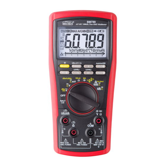
BM789
BM786
BM785
Digital
Multimeter
Table of
Contents
Previous
Page
Next
Page
1
2
3
4
5
Advertisement
Need help?
Do you have a question about the BM789 and is the answer not in the manual?
Ask a question
Questions and answers
Related Manuals for Brymen BM789
Multimeter Brymen BM780 Series User Manual
(37 pages)
Multimeter Brymen BM786 User Manual
(32 pages)
Multimeter Brymen BM821s User Manual
Brymen digital multimeter user's manual (24 pages)
Multimeter Brymen BM520s Series User Manual
(24 pages)
Multimeter Brymen BM252 User Manual
Brymen bm251; bm252; bm255; bm257 digital multimeter (17 pages)
Multimeter Brymen BM837RS User Manual
(12 pages)
Multimeter Brymen BM905s User Manual
Versatile (21 pages)
Multimeter Brymen EEVblog BM235 User Manual
(31 pages)
Multimeter Brymen BM857 User Manual
(19 pages)
Multimeter Brymen BM089 User Manual
Clamp-on multimeter (32 pages)
Multimeter Brymen BM22s User Manual
(8 pages)
Multimeter Brymen BM805s User Manual
Practical multimeters (16 pages)
Multimeter Brymen BM251s User Manual
(17 pages)
Multimeter Brymen BM079 User Manual
Clamp-on multimeter series (24 pages)
Multimeter Brymen BM859s User Manual
(17 pages)
Multimeter Brymen BM2257 User Manual
(24 pages)
This manual is also suitable for:
Bm786
Bm785
Print
Rename the bookmark
Delete bookmark?
Delete from my manuals?
Login
Sign In
OR
Sign in with Facebook
Sign in with Google
Upload manual
Upload from disk
Upload from URL


Need help?
Do you have a question about the BM789 and is the answer not in the manual?
Questions and answers