Sign In
Upload
Download
Table of Contents
Contents
Add to my manuals
Delete from my manuals
Share
URL of this page:
HTML Link:
Bookmark this page
Add
Manual will be automatically added to "My Manuals"
Print this page
×
Bookmark added
×
Added to my manuals
Manuals
Brands
Brymen Manuals
Multimeter
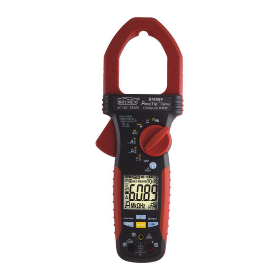
BM089
User manual
Brymen BM089 User Manual
Clamp-on multimeter
Hide thumbs
1
2
3
4
5
6
7
8
9
10
11
12
13
14
15
16
17
18
19
20
21
22
23
24
25
26
27
28
29
30
31
32
page
of
32
Go
/
32
Contents
Table of Contents
Troubleshooting
Bookmarks
Table of Contents
Terms in this Manual
International Electrical Symbols
Product Description
Operation
Maintenance
Trouble Shooting
Battery Replacement
General Specifications
Overload Protections
Low Battery
Electrical Specifications
Limited Warranty
Advertisement
Quick Links
1
Operation
Download this manual
USER'S MANUAL
BM089 & BM088 DC+AC
BM086 & BM083 AC
Table of
Contents
Previous
Page
Next
Page
1
2
3
4
5
Advertisement
Table of Contents
Need help?
Do you have a question about the BM089 and is the answer not in the manual?
Ask a question
Questions and answers
Related Manuals for Brymen BM089
Multimeter Brymen BM088 DC+AC User Manual
Clamp-on multimeter (32 pages)
Multimeter Brymen BM083 AC User Manual
Clamp-on multimeter (32 pages)
Multimeter Brymen BM086 User Manual
Clamp-on multimeter (32 pages)
Multimeter Brymen BM035 User Manual
Clamp-on multimeter (24 pages)
Multimeter Brymen BM031 User Manual
Clamp-on multimeter (24 pages)
Multimeter Brymen BM039F User Manual
Fork-clamp multimeter (20 pages)
Multimeter Brymen BM061 User Manual
Compact ac/dc clamp-on multimeter (17 pages)
Multimeter Brymen BM065 User Manual
Compact ac/dc clamp-on multimeter (17 pages)
Multimeter Brymen BM079 User Manual
Clamp-on multimeter series (24 pages)
Multimeter Brymen BM078 User Manual
Clamp-on multimeter series (24 pages)
Multimeter Brymen BM076 User Manual
Clamp-on multimeter series (24 pages)
Multimeter Brymen BM072 User Manual
Clamp-on multimeter series (24 pages)
Multimeter Brymen BM061s User Manual
Compact ac/dc clamp-on multimeter (17 pages)
Multimeter Brymen BM065s User Manual
Compact ac/dc clamp-on multimeter (17 pages)
Multimeter Brymen BM099 User Manual
Power clamp-on multimeter (32 pages)
Multimeter Brymen BM789 User Manual
(32 pages)
This manual is also suitable for:
Bm088 dc+ac
Bm083 ac
Bm086
Bm088
Bm083
Table of Contents
Print
Rename the bookmark
Delete bookmark?
Delete from my manuals?
Login
Sign In
OR
Sign in with Facebook
Sign in with Google
Upload manual
Upload from disk
Upload from URL


Need help?
Do you have a question about the BM089 and is the answer not in the manual?
Questions and answers