
Related Manuals for Brymen BM170D Series


Summary of Contents for Brymen BM170D Series
- Page 1 BRYMEN BM173D, BM175D, BM176D Mìøící a dílenské pøístroje / Klešové multimetry USER'S MANUAL DUAL SYSTEM BRIGHT PEOPLE’S CHOICE Eshop: www.emareg.cz Email: shop@emareg.cz...
- Page 2 This manual contains information and warnings that must be followed for operating the meter safely and maintaining the meter in a safe operating condition. If the meter is used in a manner not specified by the manufacturer, the protection provided by the meter may be impaired. identifies conditions and actions that could result in serious injury or even death to the user. identifies conditions and actions that could cause damage or malfunction in the instrument. To reduce the risk of fire or electric shock, do not expose this product to rain or moisture. The meter is intended only for indoor use. Keep your hands/fingers behind the hand/finger barriers (of the meter and the test probe assembly, where applicable) that indicate the limits of safe access of the hand held parts during measurements. Inspect lead wires, connectors, and probes for damaged insulation or exposed metal before using the meter. If any defects are found, replace them immediately. Only use the probe assembly provided with the meter or a UL Listed Probe Assembly to the same meter ratings or better. IEC 61010031 requires exposed conductive test probe ti CAT IV ratings. Refer to the category markings on your probe assemblies as well as on the addon accessories (like detachable Caps or Alligator Clips), if any, for applicable rating changes. Observe proper safety precautions w hen working with voltages above 33 Vrms, 46.7 Vpeak or 70 VDC. These voltage levels pose a potential shock hazard to the user.
- Page 3 Disconnect the meter from the test points before changing meter functions. Marking ofElectrical and Electronic Equipment (EEE). Do not dispose of this product as unsorted municipal waste. Contact a qualified recycler Caution! Refer to the explanation in this Manual Caution! Possibility of electric shock Earth (Ground) Meter protected throughout by Double Insulation or Reinforced insulation Fuse Direct Current(DC) Alternating Current (AC) Threephase Alternating Current Application around and removal from hazardous live conductors is permitted is applicable to test and measuring circuits connected at voltage MAINS installation. Examples are measurements on devices installed before the main fuse or circuit breaker in the building installation. is applicable to test and measuring circuits connected to voltage MAINS installation. Examples are measurements on distribution boards (including secondary meters), circuit breakers, wiring, including cables, busbars, junction boxes, switches, socket outlets in the fixed installation, and equipment for industrial use and some other equipment such as stationary motors with permanent connection to the fixed installation.
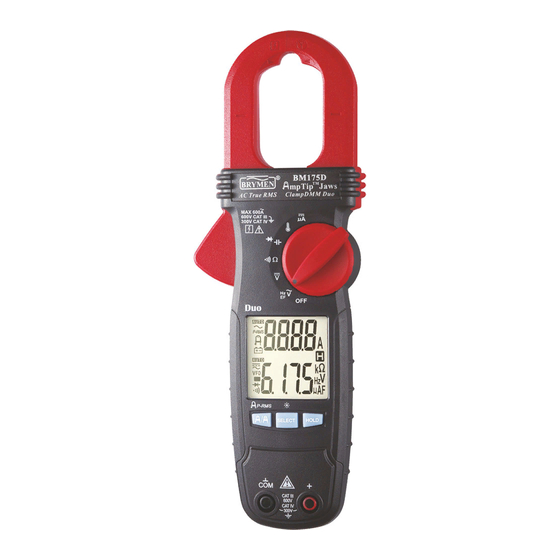
- Page 4 This user's manual uses only representative model(s) for illustrations. Please refer specification details for function availability to each model. 1) Antenna area for NonContact EF Detection 2) Jaw center indicator, at where best current accuracy is specified 3) Rotary Selector to turn the power ON/OFF and Select a function 4) 35/6 digits 6000 counts Dual numeric LCD display 5) Additional (third) input Jack for Phase Rotation function 6) Input ...
- Page 5 To realize swift simultaneous dual measurements, the meter uses two Analogto Digital Converters (Duo) for its functions (Upperdisplay readings) as well as its functions (Lowerdisplay readings) separately. functions turn ON wheneverthe function isturned ON. Defaults at function where best accuracy is specified at the jaw center area. Press button momentarily to toggle to function where best accuracy is specified near the jaw tip area for lowcurrent small conductors below 10mm in diameter. Do not use the meter to measure currents above the rated frequency (400Hz). Circulating currents may cause the magnetic circuits of the Jaws reach a hazardous temperature.
- Page 6 Note: functions are equipped with digital low pass filter, and are capable of dealing with (Variable FrequencyDrives) signals for fundamental readings. It also improves ACV and Hz reading stability being in most noisy electrical environments. The detected Electric Field strength is indicated as a series of bar graph segments on the display together with variable beep tones. Two user selectable sensitivities are available. In High Sensitivity range, the meter displays It ...
- Page 7 An antenna is located along the top right end of the stationary clamp jaw, which detects electric field surrounding energized conductors. It is ideal for tracing live wiring connections, locating wiring breakage s and to distinguish between liveand earth connections. For more precise indication of live wires, such as distinguishing between Live and Ground connections, use direct contact testing with one single test probe via an input terminal. T he COM terminal (Black) has the best sensitivity. Eshop: www.emareg.cz Email: shop@emareg.cz...
- Page 8 Inputs are madevia the test lead terminals Before and after hazardous voltage measurements, test the voltage function on a known source such as line voltage to determine proper meter functioning. Eshop: www.emareg.cz Email: shop@emareg.cz...
- Page 9 Inputs are made via the test lead terminals . Defaults at . Press button momentarily to toggle between the subject functions. Continuity function is convenient for checking wiring connections and operation of switches. The meter provides Audible as well as Visible results. A continuous beep tone, together with two flashing LCD icons , indicates a complete wire. This further improves ease of useespecially in noisy working environments. Using Resistance or Continuity function in a live circuit will produce false results and may ...
- Page 10 Inputs are madevia the test lead terminals . Defaults at . Press button momentarily to toggle between the subject functions. (For Model 173D, Capacitance and Diode functions arelocated in different rotary switch positions.) When using Diode test function , normal forward voltage drop (forward biased) for a good silicon diode is between 0.400V to 0.900V. A reading higher than that indicates a leaky diode (defective). A zero reading indicates a shorted diode (defective). An OL indicates an open diode (defective). Reverse the test leads connections (reverse biased) across the diode. The digital display shows OL if the diode is good. Any other readings indicate the diode is resistive or shorted (defective).
- Page 11 disconnected from the circuit to obtain an accurate measurement reading. 2. When using Capacitance function, discharge capacitor(s) before making any measurements. Large value capacitors should be discharged through an appropriate resistance load Inputs are madevia the test lead terminals . Press button momentarily to toggle between (Celsius) and (Fahrenheit). Be sure to insert the banana plug type K temperature bead probe Bkp60 with correct polarities. You can also use a plug adapter Bkb32 (Option al purchase) with banana pins to type K socket to adapt other type K standard mini plug temperature probes. Eshop: www.emareg.cz Email: shop@emareg.cz...
- Page 12 Inputs are madevia the test lead terminals function is designed especially for HVAC/R flame sensor applications. The 0.1 A resolution is useful for identifying the minute current changes in flame detector applications. Flame signal current check should indicate steady flame signal of at least 2 A for a rectification type, or 1.5 A for an ultraviolet type (8 A for self checking systems). If a flame signal current with inadequate strength or fluctuation beyond 10%, check the following to avoid the risk of unwanted flame relay dropout: For gas or oil flames (Minipeeper): Low supply voltage Detector location Defective detector wiring Dirty viewing windows Faulty Minipeeper For oil flames (Photocell): Detector location & wiring Smoky flame or poorly adjusted air shutter Faulty Photocell Temperature over 165 F (74 C) at photocell For gas flames (Flame Rod): Ignition interference (A flame signal current difference with the ignition both on and off greater than 0.5 A indicates the presence of ignition interference) Insufficient ground (must be at least 4 times the detector area) Flame lifting off burner head (ground), or not continuously in contact with the flame Temperature in excess of 600 F (316 C) at the flame electrode insulator causing short to ground. Eshop: www.emareg.cz Email:...
- Page 13 Inputs are made via the test lead terminals / / . Phase Rotation directions are indicated as symbolic movements by the LCD segments. Defaults at . Press button momentarilytoggles between modes. Hisensitivity mode, which detects relatively low signal outputs generated from motor spinning, for checking phase connections of Motors. Normalsensitivity mode for identifying phase sequence of Electricity Supply.
- Page 14 Connect to the Motoras illustrated.Be sure the electricity supply is removed. From the perspective of looking down the shaft of the motor, speedspin it clockwise to generate sufficient signal strength for proper meter detection. If the meter indicates a clockwise movement, the motor leads connected to L1, L2 and L3 of the meter are L1, L2 and L3 (also known as R, S and T) respectively. If the meter indicates a counte rclockwise movement, swap any two connects between the meter and motor.Then retest. Connect to the Electricity Supply as illustrated. If the meter indicates a clockwise movement, the phases connected to L1 , L2 and L3 of the meter are L1, L2 and L3 (also known as R, S and T) respectively. If the meter indicates a counter clockwise movement, swap any two connects between the meter and phases. Then retest. Connect the above mentioned L1, L2 and L3 of a Motor and that of the Electricity Supply respectively should be ...
- Page 15 The AutoPoweroff (APO) mode turns the meter off automatically to extend battery life after approximately32 minutes of nospecified activities, where applicable: 1) Rotary switch or push button operations 2) Significant measuring readings of above8.5% of ranges 3) NonOL readings for Resistance, Continuityor Diode function 4) Nonzero readings forHz function 5) Significant movement indication as in Phase Rotation functions In other words, the meter will intelligently avoid entering the APO mode when it is normal measurements. To wake up the meter from APO, press the button momentarily and release, or turn the rotary switch OFF and then back on. Always turn the rotary switch to the OFF position when the meter is not in use To avoid electrical shock, disconnect the meter from any circuit, remove the test leads from the input jacks and turn OFF the meter befo re opening the case or battery door .
- Page 16 Accuracy is specified for a period of one year after calibration . Periodic calibration at intervals of one year is recommended to maintain meter accuracy. Refer to the LIMITED WARRANTY section for obtaining calibration, repairing or warranty service. Periodically wipe the case with a damp cloth and mild detergent; do not use abrasives or solvents. If the meter is not to be used for perio ds of longer than 60 days, remove the batteries and store them separately. The meter uses standard 1.5V AAA Size (IEC R03) battery X 2 Loosen the 2 captive screws from the battery cover case . Lift the battery cover case. Replace the batteries. Replacebattery cover case. Refasten the screws. Eshop: www.emareg.cz Email: shop@emareg.cz...
- Page 17 35/6 digits 6000 counts; dual display Automatic 5 per second nominal 0 C to40 C Maximum relative humidity 80% for temperature up to 31 C decreasing linearly to 50% relative humidity at 40 C 20 C to 60 C, < 80% R.H. (with battery removed) Operating below 2000m nominal 0.15 x (specified accuracy)/ C @(0 C 18 C or 28 C 40 C), or otherwise specified True RMS Double insulation perUL/IEC/EN610101 Ed. 3.0, CAN/CSA C22.2 No. 61010 1 Ed. 3.0, UL/IEC/EN610102032 Ed. 3.0, UL/IEC/EN610102033 Ed.
- Page 18 Test lead set, User's manual, Soft carrying pouch, Bkp60 banana plug Ktype thermocouple (Models 175D & 176D only), Alligator Clip set(Model 176D only) BKB32 banana plug to typeK socket plug adaptor (Models 175D & 176D only) AmpTip lowcurrent range; Display Hold; EFDetection (NCV); Backlighted LCD; 80ms PeakRMS mode for inrush current; 3Phase Rotation detection (Models 176D only) Accuracy is (% reading dig its + number of digits) or otherwise specified, at 23 5 C.
- Page 19 Audible Threshold: Between 10 and 250 Response time: 32ms approx. RANGE Accuracy 2.0% + 4d 200.0 F, 2500 F Accuracies with film capacitor or better RANGE Accuracy 3.000V 1.5% +5d Test Current: 0.3mA typical Open Circuit Voltage: <3.5VDC typical RANGE Accuracy Burden Voltage 1.0% + 5d 200.0 A, 2000 A 3.5mV/ A 1) 2) RANGE Accuracy 40.0 C ~ 99.9 1.0% + 0.8 C ~ 400 1.0% + 1 40.0...
- Page 20 1) 2) 3) 4) RANGE Accuracy 50Hz ~60Hz 60.00A 1.5% + 5d Induced error from adjacent currentcarrying conductor: <0.06A/A Induced error from ACV measurement < 0.60A /kV @50/60Hz Add 10d to the specified accuracy @ < 6A Induced nonzero residual while beeperturns on: < 20d 1) 2) 3) 4) RANGE Accuracy 50Hz ~100Hz 60.00A , 600.0A 1.8% + 5d 100Hz ~400Hz 60.00A , 600.0A 2.0% + 5d Induced error from adjacent currentcarrying conductor: <0.06A/A Induced error from ACV measurement < 0.60A /kV @50/60Hz Specified accuracy is for measurements made at the jaw center. When the conductor...
- Page 21 BarGraph Indication EFH (High Sensitivity) EFL (LowSensitivity) Typical Voltage (Tolerance) 10V ( 5V ~25V) 40V (32V ~70V) 25V (20V ~66V) 110V (55V ~165V) 55V (50V ~125V) 220V (130V ~265V) 110V (90V ~200V) 400V (250V ~500V) 220V (>180V) 550V (>430V) Indication: Bargraph segments & audible beep tones proportional to the field strength Detection Frequency: 50/60Hz Detection Antenna: Topside of the stationary jaw ProbeContact EFDetection: For more precise indication of live wires, such as distinguishing ...
- Page 22 NOTE Eshop: www.emareg.cz Email: shop@emareg.cz...
- Page 23 NOTE Eshop: www.emareg.cz Email: shop@emareg.cz...
- Page 24 THIS WARRANTY IS EXCLUSIVE AND IS IN LIEU OF ALL OTHER WARRANTIES, EXPRESSED OR IMPLIED, INCLUDING BUT NOT LIMITED TO ANY IMPLIED WARRANTY OR MERCHANTABILITY OR FITNESS FOR A PARTICULAR PURPOSE OR USE. BRYMEN WILL NOT BE LIABLE FOR ANY SPECIAL, INDIRECT, INCIDENTAL OR CONSEQUENTIAL DAMAGES. BRYMEN TECHNOLOGY CORPORATION TEL:+886 2 2226 3396 FAX:+886 2 2225 0025 http://www.brymen.com...
Need help?
Do you have a question about the BM170D Series and is the answer not in the manual?
Questions and answers