Table of Contents
Advertisement
Quick Links
Advertisement
Table of Contents

Subscribe to Our Youtube Channel
Related Manuals for Brymen BM161


Summary of Contents for Brymen BM161
- Page 1 USER'S MANUAL BM161/BM162 Versatile AC/DC Clamp-on Multimeter Series...
-
Page 2: Overvoltage Category
1) SAFETY This manual contains information and warnings that must be followed for operating the instrument safely and maintaining the instrument in a safe operating condition. If the instrument is used in a manner not specified by the manufacturer, the protection provided by the instrument may be impaired. -
Page 3: International Electrical Symbols
WARNING To reduce the risk of fire or electric shock, do not expose this product to rain or moisture. The meter is intended only for indoor use. To avoid electrical shock hazard, observe the proper safety precautions when working with voltages above 60 VDC or 30 VAC rms. These voltage levels pose a potential shock hazard to the user. -
Page 4: Product Description
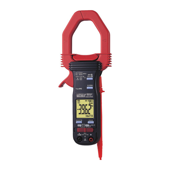
3) PRODUCT DESCRIPTION This user's manual uses only representative model(s) for illustrations. Please refer specification details for function availability to each model. 1) Hall-effect Clamp Jaw for AC & DC current electric field pick 2) Hand/Finger Barrier to indicate the limits of safe access of the meter during measurement 3) Push-buttons for special... -
Page 5: Operation
4) OPERATION DC Voltage and AC Voltage functions Inputs are made through the test lead terminals. Note: DC 400.0mV range is designed with 1000MΩ high input impedance for least current drain in measuring small signals, and can cope better with most commercially available voltage output transducers/adapters. - Page 6 ACA & DCA Current clamp-on function Inputs are made through the clamp jaws for non-invasive ACA & DCA current measurements. CAUTION (Application and removal of the Clamp-on meter) Press the jaw trigger and clamp the jaws around only one single conductor of a circuit for load current measurement.
- Page 7 CAUTION Using Resistance, Continuity or Diode function in a live circuit will produce false results and may damage the instrument. In many cases the suspected component must be disconnected from the circuit to obtain an accurate measurement reading Ω Ω Ω Ω Resistance, and Continuity functions Inputs are made through the test leads terminals.
- Page 8 Capacitance function Inputs are made through the test leads terminals. Slide-switch on defaults at Ω. Press SELECT button momentarily 3 times to select Capacitance function. Relative zero mode can be used to zero out the parasitic capacitance of the leads and the internal protection circuitry of the meter when measuring low capacitance in the order of Pico Farad (pF).
-
Page 9: Maintenance Warning
Auto Power Off (APO) When the meter is on, the Auto Power Off (APO) feature will switch the meter to sleep mode automatically after approximately 30 minutes of no slide-switch nor push button operations to extend battery life. To wake up the meter from APO, press any push-buttons momentarily or set the slide-switch to the OFF position and then slide back on again. - Page 10 Battery replacement The meter uses standard 1.5V AAA Size (NEDA 24G or IEC R03) battery X 2; or 1.5V AAA Size (NEDA 24A or IEC LR03) alkaline battery X 2. Loosen the 2 captive screws from the battery cover case. Lift the battery cover case. Replace the batteries.
-
Page 11: Specifications
6) SPECIFICATIONS General Specifications Display : 3-3/4 digits 4000 counts LCD display(s) Update Rate : 3 per second nominal Polarity : Automatic Low Battery : Below approx. 2.4V Operating Temperature : 0 C to 40 Relative Humidity : Maximum relative humidity 80% for temperature up to 31 decreasing linearly to 50% relative humidity at 40 Altitude : Operating below 2000m Storage Temperature : -20... - Page 12 Electrical Specifications Accuracy is ±(% reading digits + number of digits) or otherwise specified, at 23 C ± C & less than 75% R.H. True RMS Model 162 ACV & ACA clamp-on accuracies are specified from 5% to 100% of range or otherwise specified. Maximum Crest Factor are as specified below, and with frequency spectrums, besides fundamentals, fall within the meter specified AC bandwidth for non-sinusoidal waveforms.
- Page 13 Ohms RANGE Accuracy 0.8% + 6d 400.0Ω 0.6% + 4d 4.000kΩ, 40.00kΩ, 400.0kΩ 1.0% + 4d 4.000MΩ 2.0% + 4d 40.00MΩ Open Circuit Voltage : 0.4VDC typical Audible Continuity Tester Open Circuit Voltage: 0.4VDC typical Range: 400.0Ω; Accuracy: 1.5% + 6d Audible threshold: between 10Ω...
- Page 14 ACA Current (Clamp-on) 1) 2) RANGE Accuracy 400.0A 15Hz ~ 40Hz 2.0% + 5d 40Hz ~ 200Hz 1.5% + 5d 200Hz ~ 400Hz @ <50A 1.5% + 5d 400Hz ~ 1kHz @ <50A 2.0% + 5d 800A 15Hz ~ 40Hz @ 400A ~ 600A 2.0% + 5d 40Hz ~ 100Hz @ 400A ~ 600A 1.5% + 4d...
-
Page 15: Limited Warranty
BRYMEN's warranty does not apply to accessories, fuses, fusible resistors, spark gaps, batteries or any product which, in BRYMEN's opinion, has been misused, altered, neglected, or damaged by accident or abnormal conditions of operation or handling.
Need help?
Do you have a question about the BM161 and is the answer not in the manual?
Questions and answers