Table of Contents
Advertisement
Quick Links
Advertisement
Table of Contents

Related Manuals for Brymen BM115


Summary of Contents for Brymen BM115
- Page 1 USER'S MANUAL BM115/BM116 Versatile Clamp-on Multimeter Series...
-
Page 2: Overvoltage Category
1) SAFETY This manual contains information and warnings that must be followed for operating the instrument safely and maintaining the instrument in a safe operating condition. If the instrument is used in a manner not specified by the manufacturer, the protection provided by the instrument may be impaired. -
Page 3: International Electrical Symbols
WARNING To reduce the risk of fire or electric shock, do not expose this product to rain or moisture. The meter is intended only for indoor use. To avoid electrical shock hazard, observe the proper safety precautions when working with voltages above 60 VDC or 30 VAC rms. These voltage levels pose a potential shock hazard to the user. -
Page 4: Product Description
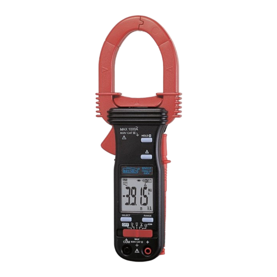
3) PRODUCT DESCRIPTION This user's manual uses only representative model(s) for illustrations. Please refer specification details for function availability to each model. 1) Transformer Clamp Jaw for AC current magnetic field pick up 2) Hand/Finger Barrier to indicate the limits of safe access of the meter during measurement 3) Push-buttons for special functions &... -
Page 5: Operation
Open input is actually a floating condition, which is not a zero-volt-input condition. Note: AC 400.0mV range selection is by RANGE button manually, and is specified from AC 40mV & up for BM115 and from AC 60mV & up for True RMS model BM116. - Page 6 CAUTION Using Resistance, Continuity or Diode function in a live circuit will produce false results and may damage the instrument. In many cases the suspected component must be disconnected from the circuit to obtain an accurate measurement reading Ω Ω Ω Ω Resistance, and Continuity functions Inputs are made through the test leads terminals.
- Page 7 Diode test function Inputs are made through the test leads terminals. Slide-switch on defaults at Ω. Press SELECT button momentarily 2 times to select Diode test function. Normal forward voltage drop (forward biased) for a good silicon diode is between 0.400V to 0.900V. A reading higher than that indicates a leaky diode (defective).
- Page 8 ACA Current clamp-on function Inputs are made through the clamp jaws for non-invasive ACA current measurements. CAUTION (Application and removal of the Clamp-on meter) Press the jaw trigger and clamp the jaws around only one single conductor of a circuit for load current measurement.
- Page 9 HOLD The hold feature freezes the display for later view. Press the HOLD button momentarily to activate and to exit the hold feature. Relative zero mode Relative zero mode allows the user to offset the meter consecutive measurements with the displaying reading as the reference value. The display will now show readings relative to the stored reference value.
-
Page 10: Maintenance
5) MAINTENANCE WARNING To avoid electrical shock, disconnect the meter from any circuit, remove the test leads from the input jacks and turn OFF the meter before opening the case. Do not operate with open case. Trouble Shooting If the instrument fails to operate, check batteries and test leads etc., and replace as necessary. - Page 11 Battery replacement The meter uses standard 1.5V AAA Size (NEDA 24A or IEC LR03) battery X 2 Loosen the 2 captive screws from the battery cover case. Lift the battery cover case. Replace the batteries. Replace battery cover case. Re-fasten the screws.
-
Page 12: Limited Warranty
BRYMEN's warranty does not apply to accessories, fuses, fusible resistors, spark gaps, batteries or any product which, in BRYMEN's opinion, has been misused, altered, neglected, or damaged by accident or abnormal conditions of operation or handling.
Need help?
Do you have a question about the BM115 and is the answer not in the manual?
Questions and answers