Table of Contents
Advertisement
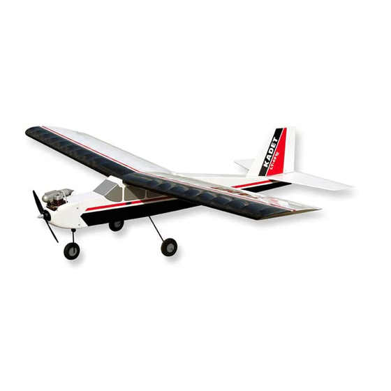
DESIGNED FOR GLOW OR ELECTRIC POWER
WARNING: Radio controlled model airplanes must be used responsibly! Just like a full-size airplane, they fly at a high rate of speed and are capable of causing serious bodily injury and
property damage if they crash. IT IS YOUR RESPONSIBILITY AND YOURS ALONE TO:
(1) Assemble this model airplane correctly according to the instructions.
(2) To ground test the model before each flight to make sure it is completely airworthy.
(3) To always fly your model in a safe approved location, away from populated areas.
(4) To always fly your model in a safe manner. Your first test flights should be made with the assistance of an experienced R/C flyer.
LIMIT OF LIABILITY: SIG Mfg. Co., Inc. guarantees this kit to be free from defects in material and workmanship at the date of purchase. The actions, skills, and attention to detail of the modeler
in assembling and flying this model airplane will ultimately determine its success and safety. Sig Mfg. Co.'s only obligation shall be to replace those parts of the kit proven to be defective or
missing. The user shall determine the suitability of the product for his or her intended use and shall assume all risk and liability in connection therewith.
SIG MFG. CO., INC. PO Box 520 Montezuma, IA 50171-0520
www.sigmfg.com
Kit No. SIGRC67EGARF
Wingspan: 70 in. (1778 mm)
Wing Area: 900 sq.in. (58.1 dm
Length: 57 in. (1447 mm)
Flying Weight: 6 - 6.25 lbs. (2720-2835 g)
Wing Loading: 15-16 oz./sq.ft. (47-49 g/dm
Radio: 4 Channel with 4 Standard Servos
Glow:
.40-.46 cu.in. (6.5-7.5cc) 2-Stroke Engine
.40-.54 cu.in. (6.5-8.8cc) 4-Stroke Engine
Electric:
500 watt (3528-1000kv) Motor
© Copyright 2011, SIG Mfg. Co., Inc.
)
2
)
2
Advertisement
Table of Contents

Related Manuals for SIG KADET LT-40 EG


Summary of Contents for SIG KADET LT-40 EG
- Page 1 (4) To always fly your model in a safe manner. Your first test flights should be made with the assistance of an experienced R/C flyer. LIMIT OF LIABILITY: SIG Mfg. Co., Inc. guarantees this kit to be free from defects in material and workmanship at the date of purchase. The actions, skills, and attention to detail of the modeler in assembling and flying this model airplane will ultimately determine its success and safety.
-
Page 2: Assembly Manual
Welcome to the sport of Radio Control flying, and thank you for 5161 East Memorial Drive choosing the SIG KADET LT-40 EG ARF. In order for your KADET Muncie, IN 47302 to fly as well as it was designed to, it must be properly assembled. - Page 3 - see your ESC manual for more guidance. Alcohol or Acetone For Epoxy Clean-up 1/2” Thick Soft Foam Rubber (such as SIG #RF-240) - Used to 3 or 4 cell 4500mAh LITHIUM-POLYMER BATTERY PACK protect your radio receiver and battery from vibration. Also...
- Page 4 Please check the contents of your kit box with these diagrams. If any parts are missing, contact SIG Mfg. Co. at 641-623-5154. Note: Not all parts are shown at same scale.
- Page 5 Please check the contents of your kit box with these diagrams. If any parts are missing, contact SIG Mfg. Co. at 641-623-5154. COMPLETE KIT PARTS LIST (1) Nylon Nose Gear Steering Bearing The following is a complete list of all parts contained in this kit.
-
Page 6: Covering Material
(6) Nylon R/C Links; for ail(2); rud(2); elev(2) wood typically loses this moisture, dimensionally "shrinking" in the process. In turn, this may cause some wrinkles. However, (2) Brass Pushrod Connector; for thro(1); nose gear(1) wrinkles are easy to remove by just using a hobby type heat iron. (2) Pushrod Connector Retainer;... -
Page 7: Wing Assembly
NOTE: ANY REFERENCE TO RIGHT OR LEFT IN THIS 4) Apply a liberal amount of Epoxy Glue to the end ribs of BOTH MANUAL REFERS TO YOUR RIGHT OR LEFT AS IF YOU WERE Wing Panels and to the exposed end of the Wing Joiner. SEATED IN THE COCKPIT OF THE AIRPLANE. -
Page 8: Apply The Decals
Once you have it in position, use a piece of stiff cardboard (or sheet balsa, thin plywood, or a SIG SH678 Epoxy Spreader) to squeegee the excess soapy water out from under the decal. -
Page 9: Fuselage Assembly
5) Remove the Stabilizer from the Fuselage and carefully strip FUSELAGE ASSEMBLY away the covering material on the bottom, between the two lines, 1) Draw a center-line on the area of the Fuselage where the where the Stabilizer will be glued to the Fuselage. CUT THE Stabilizer will be mounted. -
Page 10: Landing Gear Assembly
LANDING GEAR ASSEMBLY Locate the following parts from the kit contents: (2) 4.5mm formed Main Landing Gear Wires (2) 3” dia. Main Wheels (2) 4.5mm id Plastic Wheel Spacers (2) 4.5mm Wheel Collars (2) Nylon Landing Gear Straps (4) M3 x 10mm Screws (1) 4mm formed Nose Gear Wire (1) 2-3/4"... -
Page 11: Glow Engine Installation
The installation for either a 2-stroke or 4-stroke glow engine is basically the same. The only differences being in the throttle arm locations on the carburetors and the muffler locations. The factory- installed throttle pushrod sleeve in the fuselage has been placed to exit the firewall on the right side of the fuselage. - Page 12 Adjust as many times as necessary to make sure that the Propeller comes out the center of the openings. THE PROPELLER MUST NOT TOUCH THE SPINNER! When you have it in the right position, tighten the Prop Nut. 4) Install the Spinner to the Backplate using the two small Screws provided.
- Page 13 4) Put the plain end of a #47 drill bit about 1/4" inside the back end 8) Trial fit the tank in place inside the fuselage to familiarize of the vent tube. Using the drill bit for leverage, slowly bend the yourself with how it mounts.
- Page 14 of fuel line tubing. The fuel lines should be kept as short as quickly made by measuring the diameter of the engine head and possible for best fuel draw, but not so short that there is danger of the overall length of the engine. It will serve as an undersize them coming off in flight.
- Page 15 THROTTLE PUSHROD 7) Slide the unbent end of the throttle pushrod wire inside the Locate the following parts from the kit contents: plastic outer sleeve as you re-bolt your engine/engine mounts to (1) Nylon Outer Pushrod Sleeve (already in the fuselage) the firewall.
-
Page 16: Electric Motor Installation
pushrod wire at the carburetor. If necessary, re-bend the wire to eliminate the bind. If the throttle servo is binding or “stalling” because it has too much travel compared to the carburetor travel, try using your transmitter’s “End Point Adjustment” feature to dial in the proper amount of travel. - Page 17 Bolt your motor and mount onto the firewall. Use thread c) Mount your ESC inside the nose of the airplane, just behind locking compound (not supplied) on all the bolt threads. the firewall. Stick it to the fuselage bottom with a 1-1/2” long piece of 3/4”...
-
Page 18: Radio Installation
10) OPTIONAL SPINNER: A 2” dia. spinner is included in this kit. grommets so far that the grommets loose all shock absorbing No doubt it will be used by almost everyone who is installing a glow ability. Tighten the screws just enough to make contact with the engine. -
Page 19: Rudder Pushrod
1) Hold the Nylon Control Horn in position on the left side of the rudder and mark the location of the mounting holes. Drill pilot holes through the rudder with a 1/16" dia. drill bit (turn the bit with your fingers or a pin vise - a power drill is not necessary). 6) Slide the unbent end of the pushrod wire inside the plastic outer sleeve, starting from the servo end. -
Page 20: Elevator Pushrod
the transmitter's rudder control stick, the rudder should move approximately 1" right and 1" left. NOTE: If you are not getting the correct amount of rudder travel, try using your transmitter’s “End Point Adjustment” feature to dial in the proper amount. Also fine tune the overall length of the rudder pushrod, by screwing one or both of the nylon R/C Links further in or out, until the rudder is neutral when the transmitter is neutral. -
Page 21: Aileron Pushrods
5) Clip another R/C Link into the elevator servo arm. Set the elevator in neutral position. Mark the servo end of the pushrod tube exactly 1/8" from the end of the R/C Link. Unhook the R/C Link from the elevator horn and slide the pushrod tube back out of the airplane. - Page 22 find the cause and fix it now. With full right and left movement of a) Drill a 1/16" dia. hole completely through the bottom of the the transmitter's aileron control stick, the ailerons should move fuselage a couple inches behind the main landing gear. This hole approximately 3/8"...
- Page 23 BALANCE YOUR AIRPLANE! MAKING A “Z-BEND” (In 5 Easy Steps) We know that your KADET LT-40 looks done and you’re anxious to Step 1: Using a pencil or go out and fly it, BUT WAIT A MINUTE - IT’S NOT REALLY DONE felt-tip pen, put a mark 1/4”...
-
Page 24: Find A Safe Place To Fly
PRE-FLIGHT CHECKOUT LEARNING TO FLY R/C Be certain to range check your radio equipment according to Learning to fly radio control model airplanes is not a skill you will the manufacturer’s instructions before attempting to fly. learn in a few minutes. It’s very similar to learning to fly a real airplane in that you should enlist the help of an instructor before Run your engine for the first time on the ground.
Need help?
Do you have a question about the KADET LT-40 EG and is the answer not in the manual?
Questions and answers