Table of Contents
Advertisement
Quick Links
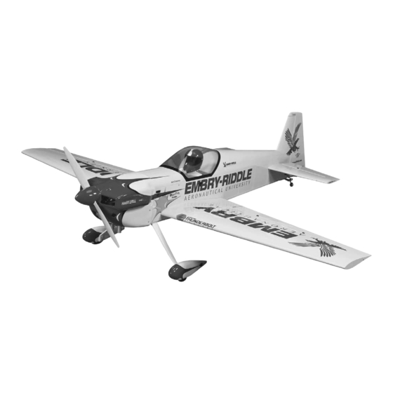
Wingspan: 50 in [1270mm]
2
Wing Area: 494 sq in [31.9 dm
]
Weight: 3.25–3.5 lb [1475–1590 g]
Wing Loading: 15 – 16 oz/sq ft [46–49 g/dm
Length: 47.75 in [1215mm]
Radio: 4 channel radio (minimum) or 5 channel computer radio with mixing
capabilities (for separate ailerons).
™
Motor: RimFire
.32 (42-50-800kV)
®
Great Planes
Model Manufacturing Co. guarantees this kit to
be free from defects in both material and workmanship at the date
of purchase. This warranty does not cover any component parts
damaged by use or modifi cation. In no case shall Great Planes'
liability exceed the original cost of the purchased kit. Further,
Great Planes reserves the right to change or modify this warranty
without notice.
In that Great Planes has no control over the fi nal assembly or
material used for fi nal assembly, no liability shall be assumed nor
accepted for any damage resulting from the use by the user of
the fi nal user-assembled product. By the act of using the user-
assembled product, the user accepts all resulting liability.
If the buyer is not prepared to accept the liability associated
with the use of this product, the buyer is advised to return
READ THROUGH THIS MANUAL BEFORE STARTING CONSTRUCTION. IT CONTAINS IMPORTANT
INSTRUCTIONS AND WARNINGS CONCERNING THE ASSEMBLY AND USE OF THIS MODEL.
Entire Contents © Copyright 2008
2
]
WARRANTY
this kit immediately in new and unused condition to the place
of purchase.
To make a warranty claim send the defective part or item to Hobby
Services at the address below:
Hobby Services
3002 N. Apollo Dr., Suite 1
Champaign, IL 61822 USA
Include a letter stating your name, return shipping address, as
much contact information as possible (daytime telephone number,
fax number, e-mail address), a detailed description of the problem
and a photocopy of the purchase receipt. Upon receipt of the
package, the problem will be evaluated as quickly as possible.
Champaign, Illinois
(217) 398-8970, Ext 5
airsupport@greatplanes.com
INSTRUCTION MANUAL
GPMA1573Mnl1.0
Advertisement
Table of Contents

Related Manuals for GREAT PLANES Eagle 580


Summary of Contents for GREAT PLANES Eagle 580
-
Page 1: Instruction Manual
Hobby Services 3002 N. Apollo Dr., Suite 1 In that Great Planes has no control over the fi nal assembly or Champaign, IL 61822 USA material used for fi nal assembly, no liability shall be assumed nor accepted for any damage resulting from the use by the user of Include a letter stating your name, return shipping address, as the fi... -
Page 2: Table Of Contents
TABLE OF CONTENTS INTRODUCTION The full scale Eagle 580 is the choice of air show performer INTRODUCTION ............... 2 Mat Chapman. This Mudry Cap has been designated the SAFETY PRECAUTIONS ..........2 “Eagle” by Matt because of the 330 HP Lycoming that powers DECISIONS YOU MUST MAKE ........ -
Page 3: Decisions You Must Make
Always wear safety goggles, a particle mask and rubber gloves when grinding, drilling and The Eagle 580 EP ARF comes with a mounting box for sanding fi berglass parts. Vacuum the parts and the work the Great Planes RimFire brushless out-runner motor. -
Page 4: Additional Items Required
This is the list of adhesives and building supplies required 30-minute (or 45-minute) epoxy or 6-minute epoxy. When to fi nish the Eagle 580 EP. Order numbers are provided 30-minute epoxy is specifi ed it is highly recommended that in parentheses. -
Page 5: Ordering Replacement Parts
Order Number Description How to Purchase Missing pieces ..Contact Product Support Replacement parts for the Eagle 580 are available using the Instruction manual Contact Product Support order numbers in the Replacement Parts List that follows. The Full-size plans ......Not available... -
Page 6: Preparations
Apply pressure over sheeted areas to thoroughly bond the covering to the wood. Caution: The Eagle 580 ❏ ❏ 4. Install the servo into the servo opening. Install and... -
Page 7: Assemble The Fuselage
❏ ❏ 7. Install and then remove a #2 x 3/8" [9.5mm] screw ASSEMBLE THE FUSELAGE into each of the holes you have drilled. Apply a drop of thin CA into the holes to harden the threads. Once the glue has cured, Install the Main Landing Gear secure the control horn to the aileron with the screws. -
Page 8: Install The Rudder
❏ ❏ ❏ 2. Use a sharp #11 blade to cut a strip of covering from 2. Attach the main landing gear to the fuselage with the hinge slots in the wing and aileron. two 4-40 x 1/2" [13mm] SHC screws, #4 lock washers and #4 fl... -
Page 9: Install The Tail Gear
Install the Tail Gear ❏ 3. Insert the wire from the tail gear through the nylon stud in the bottom of the rudder. ❏ 1. Glue the nylon tail gear bushing in the hole in the aft bottom of the fuse. ❏... -
Page 10: Install The Stabilizer
Install the Stabilizer ❏ 3. Install the elevator joiner wire into the stab opening in the fuselage. ❏ 1. Remove the canopy from the fuselage. Do this by sliding the canopy forward towards the fi rewall and then lifting the back of the canopy. - Page 11 ❏ 5. Once you are satisfi ed with the alignment of the stab, glue the stab in position in the fuselage. Carefully wick small amounts of thin CA into the stab/fuselage to secure the stab. You can now remove the wings and continue with the assembly of the fuselage.
-
Page 12: Install The Motor
Install the Motor INSTALL THE RADIO SYSTEM The Eagle 580 EP has been designed to use the Great Install the Elevator Servo Planes RimFire .32 (42-50-800kV) Out-runner Brushless motor. If you will be installing a different motor, you may need to modify the plywood motor box. -
Page 13: Install The Receiver
Install the Receiver Before installing the rudder servo you need to complete the installation of the receiver and battery. To properly set up the rudder pull-pull system you will need to be able to operate the servos. ❏ 4. Thread a nylon clevis 20 turns onto a 2-56 x 6" [152mm] wire pushrod. -
Page 14: Install The Rudder Servo
point of a hobby knife to help pull the string through the exit. Install the Rudder Servo Tape the string to the side of the fuselage to prevent it from being pulled through while installing the rudder horns. Now is the time you need to decide on which rudder control method you are going to use. -
Page 15: Apply The Decals
on the other side of the fuselage. With the rudder and the rudder servo arm centered, pull the string tight at the rudder and squeeze the crimps to secure the strings. Apply a drop of CA to the string and cut off the excess string. APPLY THE DECALS The following photographs and the box photographs show the location of the decals on the airplane. -
Page 16: Get The Model Ready To Fly
Be certain the control surfaces IMPORTANT: The Eagle 580 EP has been extensively have remained centered. Adjust if necessary. fl own and tested to arrive at the throws at which it fl ies best. -
Page 17: Finish The Model
ESC while balancing the model. weight must be added to the tail to balance. If additional ❏ weight is required, use Great Planes (GPMQ4485) “stick 5. Install the canopy. on” lead. A good place to add stick-on nose weight is to the motor box (don’t attach weight to the cowl—it is not intended... -
Page 18: Balance The Model Laterally
We use a Top Flite Precision Magnetic Prop Balancer PREFLIGHT (TOPQ5700) in the workshop and keep a Great Planes Fingertip Prop Balancer (GPMQ5000) in our fl ight box. Identify Your Model No matter if you fl y at an AMA sanctioned R/C club site or Range Check if you fl... -
Page 19: Motor Safety Precautions
Radio Control ELECTRIC MOTOR SAFETY PRECAUIONS 1) I will have completed a successful radio equipment ground check before the fi rst fl ight of a new or repaired model. Failure to follow these safety precautions may result 2) I will not fl y my model aircraft in the presence of spectators in severe injury to yourself and others. -
Page 20: Flying
fl utter. Flutter occurs when a control surface (such as an aileron or elevator) or a fl ying surface (such as a Take it easy with the Eagle 580 EP for the fi rst fl ight, gradually wing or stab) rapidly vibrates up and down (thus causing getting acquainted with it as you gain confi... -
Page 21: Landing
Landing 3D FLYING To initiate a landing approach, lower the throttle while on the Because of the power-to-weight ratio on 3D planes, straight- downwind leg. Allow the nose of the model to pitch downward and-level fl ight should be at a reduced throttle and full power to gradually bleed off altitude. - Page 22 KNIFE EDGE TUMBLE pull back on the elevator while reducing throttle. The nose of the plane should come up. Depending on the plane/set- up, you may have to make constant aileron (wing walking) and rudder corrections for this maneuver. As the nose of the plane comes up, start adding in a little bit of power to help maintain airspeed.
- Page 23 Eagle 580. Its digitally enhanced microprocessor ranging from park flyers to 1.60-size giants! Their high- speeds response time, while two ball bearings, metal...
Need help?
Do you have a question about the Eagle 580 and is the answer not in the manual?
Questions and answers