Table of Contents
Advertisement
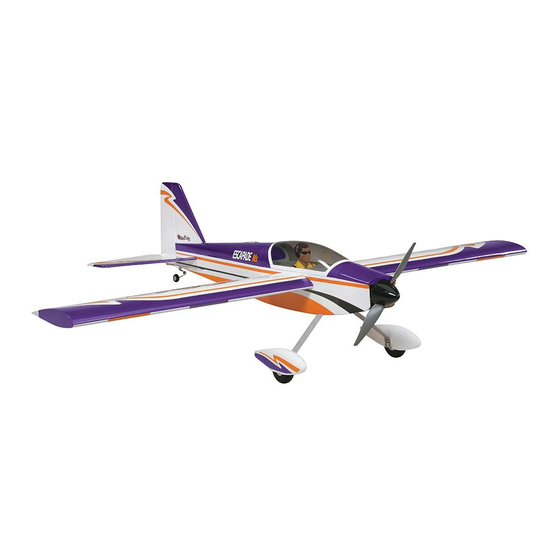
SPECIFICATIONS
Wingspan: 52 in [1320 mm]
Wing Area: 449 in
Wing Loading: 26−28 oz/ft
[79−85 g /dm
WARRANTY
Great Planes
®
Model Manufacturing Co. guarantees this kit to
be free from defects in both material and workmanship at the
date of purchase. This warranty does not cover any component
parts damaged by use or modification. In no case shall Great
Planes' liability exceed the original cost of the purchased kit.
Further, Great Planes reserves the right to change or modify this
warranty without notice.
In that Great Planes has no control over the final assembly or
material used for final assembly, no liability shall be assumed nor
accepted for any damage resulting from the use by the user of
the final user-assembled product. By the act of using the
user-assembled product, the user accepts all resulting liability.
If the buyer is not prepared to accept the liability associated
with the use of this product, the buyer is advised to return
READ THROUGH THIS MANUAL BEFORE STARTING CONSTRUCTION. IT CONTAINS IMPORTANT
INSTRUCTIONS AND WARNINGS CONCERNING THE ASSEMBLY AND USE OF THIS MODEL.
© 2013 Great Planes Model Mfg. A subsidiary of Hobbico, Inc.
I N S T R U C T I O N
Length: 45 in [1145mm]
2
2
Weight: 5 − 5.5 lb [2270−2490 g]
[29 dm
]
Radio: 4-channel radio system with 5 servos
2
2
]
Engine: .46−.55 in
Electric Motor: RimFire™ .46-.55, 60A ESC
3
[7.45–9.0cc] two-stroke, .52 – .70 in
this kit immediately in new and unused condition to the
place of purchase.
To make a warranty claim send the defective part or item to
Hobby Services at the address below:
3002 N. Apollo Dr. Suite 1
Champaign IL 61822 USA
Include a letter stating your name, return shipping address, as
much contact information as possible (daytime telephone
number, fax number, e-mail address), a detailed description of
the problem and a photocopy of the purchase receipt. Upon
receipt of the package the problem will be evaluated as quickly
as possible.
airsupport@greatplanes.com
™
M A N U A L
Battery: One 4S 3350mAh 14.8V LiPo
3
[8.5 – 11.1cc] four-stroke
Hobby Services
Champaign, Illinois
(217) 398-8970, Ext 5
GPMA1202 Mnl
Advertisement
Table of Contents

Related Manuals for GREAT PLANES Escapade Mx


Summary of Contents for GREAT PLANES Escapade Mx
- Page 1 3002 N. Apollo Dr. Suite 1 Champaign IL 61822 USA In that Great Planes has no control over the final assembly or material used for final assembly, no liability shall be assumed nor Include a letter stating your name, return shipping address, as...
-
Page 2: Table Of Contents
For the latest technical updates or manual corrections to the Protect Your Model, Yourself & Others… Escapade MX ARF visit the Great Planes web site at www. Follow These Important Safety Precautions greatplanes.com. Open the “Airplanes” link, then select the 1. -
Page 3: Decisions You Must Make
❍ 3' Great Planes Silicone Fuel Tubing (GPMG4131) performance or safety of your completed model. ❍ (1) Great Planes Aluminum Fuel Line Plug (GPMQ4166) Remember: Take your time and follow the instructions to end up with a well-built model that is straight and true. -
Page 4: Additional Items Required
3/4" [19mm] long with forty threads per inch. To locate a hobby dealer, visit the Great Planes web site at ● When you see the term test fi t in the instructions, it means www.greatplanes.com. Select “Where to Buy” in the menu across the top of the page and follow the instructions provided that you should fi... -
Page 5: Kit Contents
® number and GPMA2001 Fuselage Escapade Mx ARF expiration date for payment. GPMA2002 Horizontal Stabilizer Escapade Mx ARF Mail parts orders and payments by personal check to: GPMA2003 Vertical Stabilizer Mx Escapade ARF Hobby Services GPMA2004 Canopy Escapade Mx ARF... -
Page 6: Tighten The Covering
TIGHTEN THE COVERING Refer to the separate instruction sheet titled How To Tighten Covering On ARF Models. Follow the instructions to tighten the covering. If you prefer to get started on assembly right away, the tightening process could be done later (but it is usually easiest to do while the model is still in separate pieces). -
Page 7: Assemble The Fuselage
ASSEMBLE THE FUSELAGE Install the Elevator and Rudder ❏ ❏ 6. Thread a nylon clevis approximately 20 turns onto the threaded end of the 2-56 x 6" [152mm] wire and then slide a silicone clevis keeper onto the wire. Install the clevis into the control arm as shown in the photograph. - Page 8 Add a drop of threadlocker to the threads of the wires. Then, tighten the assembly to the fuselage with #4 fl at washers and a 4-40 lock nut on each rod. The included socket tool may be used to tighten the nuts. These should be snug, but do not overtighten and crush the stab.
-
Page 9: Mount The Main Landing Gear
❏ D. Using the holes in the strap as a guide, drill 1/16" [1.6mm] holes into the bottom of the fuselage. Install, then remove two #2 x 3/8" [9.5mm] self-tapping screws into the holes, apply a few drops of thin CA to the holes, allow to harden, and remount the strap with the screws. -
Page 10: Mount The Electric Motor
❏ 3. On the bottom of the plywood electric motor mount you will fi nd two mounting holes for the Great Planes 60 amp ESC (GPMM1850). Drill a 1/16" [1.6mm] hole in the location shown at the back of the mount. Insert and then remove a #3 x 3/8"... -
Page 11: Mount The Battery
Mount the Battery IMPORTANT: If powering your Escapade with an electric motor, before experimenting with different motor battery combinations and connecting multiple battery packs with adapter plugs, refer to the Battery Precautions on page 22. ❏ 5. Use a side cutter or Moto-Tool to cut the screws fl ush with the surface of the plywood. -
Page 12: Install The Motor Cover And Spinner
Install the Motor Cover and Spinner ❏ 3. Next use clear tape to secure the brushless cover’s sides to the fuselage sides. ❏ ❏ 4. Use a felt tipped marker to mark the locations for the 1. Place the included balsa stick on the nose of the Escapade brushless cover’s securing screws which will go through the MX as shown. -
Page 13: Mount The Fuel Tank
screw in the stopper assembly a few turns and temporarily remove the stopper assembly from the tank. Be certain the vent tube is toward the top of the tank. Then, reinsert the stopper assembly and tighten the screw to squish the rubber stopper and seal the tank. - Page 14 3. Use a marker to mark the position for the throttle pushrod ❏ ™ 5. Use a Great Planes Dead Center Hole Locator as shown on the fi rewall pictured. Use a 13/64” drill bit to drill (GPMR8130) or a sharpened wire to mark the location of through the fi...
-
Page 15: Hook Up The Throttle
the servo bay. Cut the nylon pushrod tube so it extends from HOOK UP THE THROTTLE the fi rewall by at least 1/4" [6mm]. Roughen the end of the tube with 180 grit sandpaper. Apply a couple of drops of CA glue where the tube passes through the fi... -
Page 16: Install The Fuel Line
Install the Fuel Line FINAL ASSEMBLY Final Radio Installation Vent / Overflow (Connect to fitting on Muffler) One line is for Fueling and Defueling. The other line goes to the Carburetor. It doesn’t matter which line goes where because they are both the same inside the fuel tank. ❏... -
Page 17: Install The Propeller And Spinner
new holes). Note: For glow engines the switch should be mounted on the side of the fuselage opposite the muffl er. Cut the covering from the switch mount holes and mount the on/ off switch. Then connect the switch to the radio and battery. Install the Propeller and Spinner ❏... -
Page 18: Install The Wings
Install the Wings ❏ 4. Insert the other aileron servo extension into the dual servo extension. Use heat shrink tubing to secure the servo ❏ connections to the dual servo extension. 1. Insert the wing joiner into one of the wing panels. Insert the aileron servo extension connector into the dual servo extension. -
Page 19: Check The Control Directions
Check the Control Directions These are two 3200mAh batteries (one 11.1V and the other 7.4V). When joined in SERIES, ❏ 1. Turn on the transmitter and receiver and center the trims. the result will be an 18.5V, 3200mAh battery. If necessary, remove the servo arms from the servos and reposition them so they are centered. -
Page 20: Balance The Model (C.g.)
Move the control surface and move your ❏ ™ 1. If using a Great Planes C.G. Machine , set the rulers to ruler forward. Read the measurement to get 2.75" [70mm]. If not using a C.G. Machine, use a fi ne-point the throw. -
Page 21: Balance The Model Laterally
2 oz. [57g] weight). If spinner weight is not practical or batteries that are only partially charged. is not enough, or if tail weight is required, use Great Planes “stick-on” lead (GPMQ4485). To fi nd out how much weight is... -
Page 22: Ground Check And Range Check
Ground Check and Range Check AMA SAFETY CODE (excerpts) Run the engine for a few minutes, making sure it idles reliably, Read and abide by the following excerpts from the Academy transitions smoothly and maintains full power indefi nitely. of Model Aeronautics Safety Code. For the complete Safety Afterward, shut the engine off and inspect the model closely, Code refer to Model Aviation magazine, the AMA web site or making sure all fasteners, pushrods and connections have... -
Page 23: Check List
CHECK LIST FLYING The Escapade is a great-fl ying model that fl ies smoothly and During the last few moments of preparation your mind may predictably. The Escapade does not, however, possess the be elsewhere anticipating the excitement of the fi rst fl ight. self-recovery characteristics of a primary R/C trainer and Because of this, you may be more likely to overlook certain should be fl... -
Page 24: Flight
control. Level the attitude when the model reaches the runway Flight threshold, modulating the throttle as necessary to maintain your glide path and airspeed. If you are going to overshoot, For reassurance and to keep an eye on other traffi c, it is a smoothly advance the throttle (always ready on the right rudder good idea to have an assistant on the fl...
Need help?
Do you have a question about the Escapade Mx and is the answer not in the manual?
Questions and answers