Table of Contents
Advertisement
Quick Links
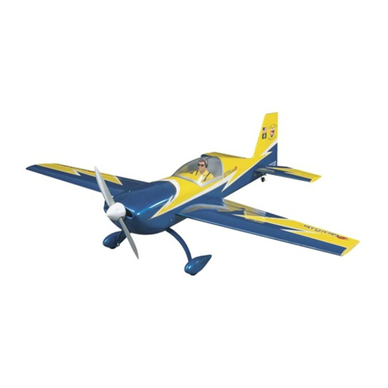
Wingspan: 55in [1395mm]
2
2
Wing Area: 590 in
[38.1 dm
]
Weight: 5.5–6.5 lb [2495–2950 g]
2
Wing Loading: 21–25 oz/ft
[66–77 g/dm
Length: 53 in [1345mm]
Radio: 4-5 channel, 4-5 servos
Engine: 0.46–0.55 cu in [7.5–9cc] two-stroke, 0.52–0.81 cu in [8.5–13cc] four-stroke
Electric Motor: RimFire .80 [50-55-500kV] with Silver Series 60A ESC
Great Planes
®
Model Manufacturing Co. guarantees this kit to
be free from defects in both material and workmanship at the date
of purchase. This warranty does not cover any component parts
damaged by use or modifi cation. In no case shall Great Planes'
liability exceed the original cost of the purchased kit. Further,
Great Planes reserves the right to change or modify this warranty
without notice.
In that Great Planes has no control over the fi nal assembly or
material used for fi nal assembly, no liability shall be assumed nor
accepted for any damage resulting from the use by the user of
the fi nal user-assembled product. By the act of using the user-
assembled product, the user accepts all resulting liability.
If the buyer is not prepared to accept the liability associated
with the use of this product, the buyer is advised to return
READ THROUGH THIS MANUAL BEFORE STARTING CONSTRUCTION. IT CONTAINS IMPORTANT
INSTRUCTIONS AND WARNINGS CONCERNING THE ASSEMBLY AND USE OF THIS MODEL.
Entire Contents © Copyright 2008
INSTRUCTION MANUAL
2
]
WARRANTY
this kit immediately in new and unused condition to the place
of purchase.
To make a warranty claim send the defective part or item to Hobby
Services at the address below:
Hobby Services
3002 N. Apollo Dr., Suite 1
Champaign, IL 61822 USA
Include a letter stating your name, return shipping address, as
much contact information as possible (daytime telephone number,
fax number, e-mail address), a detailed description of the problem
and a photocopy of the purchase receipt. Upon receipt of the
package, the problem will be evaluated as quickly as possible.
Champaign, Illinois
(217) 398-8970, Ext 5
airsupport@greatplanes.com
GPMA1022Mnl1.0
Advertisement
Table of Contents

Related Manuals for GREAT PLANES EXTRA-300SP


Summary of Contents for GREAT PLANES EXTRA-300SP
- Page 1 Hobby Services 3002 N. Apollo Dr., Suite 1 In that Great Planes has no control over the fi nal assembly or Champaign, IL 61822 USA material used for fi nal assembly, no liability shall be assumed nor accepted for any damage resulting from the use by the user of Include a letter stating your name, return shipping address, as the fi...
-
Page 2: Table Of Contents
RC aerobatic fl ight. Great lengths have been taken to ensure ELECTRIC MOTOR AND SAFETY PRECAUTIONS ..3 the Great Planes Extra 300SP .46 ARF is able to fulfi ll the DECISIONS YOU MUST MAKE ........3 demands of the most critical modeler. Whether you desire to Glow Engine Accessories .......... -
Page 3: Electric Motor And Safety Precautions
1. Your Great Planes Extra 300SP .46 ARF should not be the performance or safety of your completed model. considered a toy, but rather a sophisticated, working model that functions very much like a full-size airplane. -
Page 4: Electric Motor Accessories
Ailerons: 45 in-oz However, the following setup is one that has been tested with Rudder: 70 in-oz the Great Planes Extra 300SP .46 ARF and has proven to Throttle (Glow Setup Only): 20 in-oz have the best overall performance. ❏... -
Page 5: Additional Items Required
❏ CA Debonder (GPMR6039) Great Planes Pro ™ CA Glue Thin (GPMR6002) ❏ ❏ Epoxy Brushes (GPMR8060) Great Planes Pro CA Glue Thick (GPMR6014) ❏ ❏ Mixing Sticks (GPMR8055) Great Planes Pro Epoxy 6-Minute (GPMR6042) ❏ ❏ Mixing Cups (GPMR8056) Great Planes Pro Epoxy 30-Minute (GPMR6043) ❏... -
Page 6: Ordering Replacement Parts
Frequently you can study photos in following steps to get another view of the same parts. To locate a hobby dealer, visit the Great Planes web site at www.greatplanes.com. Choose “Where to Buy” at the • The Great Planes Extra 300SP .46 ARF is factory-covered bottom of the menu on the left side of the page. -
Page 7: Kit Inspection
Product Support. When reporting defective or missing parts, use the part names exactly as they are written in the Kit Contents list. Great Planes Product Support 3002 N. Apollo Drive, Suite 1 Champaign, IL 61822 Telephone: (217) 398-8970, ext. -
Page 8: Shrink The Covering
SHRINK THE COVERING ❏ 3. Insert one half of each hinge into the aileron. ❏ Examine the airframe for wrinkles in the covering or areas where the covering isn’t adhered to the structure. Where necessary, use a covering iron with a protective covering sock to shrink any wrinkles and get the covering bonded to the framework—use an iron temperature setting lower than you normally would for MonoKote—around 300°... -
Page 9: Install The Wing Dowels
drops of thin CA glue to each side, of each hinge. At this point Install the Aileron Servos do not fl ex the hinge. Wipe off any excess CA that appears in the gap and set the wing aside. Repeat steps 1-7 for the ❏... - Page 10 ❏ ❏ 4. Using a 1/16" [1.5mm] drill bit, drill a hole through the blocks at the locations you just marked. Tap the hole by screwing the servo mounting screws that came with your servo into the holes and then removing them. Harden the threads in the block by adding two drops of thin CA glue into each hole.
-
Page 11: Assemble The Fuselage
Screw the clevis onto the threaded end of the pushrod by rotating Attach the Horizontal Stabilizer the clevis 18 complete revolutions. A Great Planes 4-in-1 Installation Tool (GPMR8035) makes this task much easier. ❏ ❏ 13. Place the clevis in the control horn without snapping it shut. - Page 12 covering in between the marks and the already cut portion of the covering, remove that section of the covering. Be careful not to cut into the wood when removing the covering. ❏ 3. Once the trailing edge of the stabilizer has been centered, insert a T-pin in both sides of the trailing edge as shown.
-
Page 13: Hinge The Rudder And Elevators
❏ ❏ 7. View the stabilizer standing approximately 6' [2.5m] 3. Test fi t the tail wheel into both the fuselage and the rudder behind the airplane. Make sure the horizontal stabilizer and as shown. If the tail wheel does not fi t properly, use a hobby the wing are aligned. -
Page 14: Landing Gear Installation
Landing Gear Installation Install the Elevator Servo ❏ 1. Locate the main landing gear, axles, wheels, wheel collars, set screws, wheel pants, and four 4-40 SHCS. Attach the axles to the landing gear. Make a mark on the landing gear 5/16" ❏... -
Page 15: Install The Hatch
screws. Using a 1/16" [1.5mm] drill bit, drill a guide hole at the marks you just made. Install the elevator servo. Remove the elevator servo and place 2 drops of thin CA in each of the elevator mounting screw holes. Wait for the CA to fully cure. -
Page 16: Install The Electric Motor And Rudder Servo
CA or 6 minute epoxy around the washer to fully secure it to the fuselage. ❏ 2. To use the Great Planes Large Electric Motor Mount (GPMG1260) with this model, you’ll need to make a few ❏... - Page 17 Verify that the motor rotation is correct. Disconnect the batteries and receiver. Note: If using the Great Planes SS-60 ESC you will need to plug a battery into the receiver, because the Great Planes SS-60 ESC does not have a Battery Eliminator Circuit (BEC).
- Page 18 ❏ ❏ 9. Installing the rudder servo in the tray is very similar to 12. With the rod secure, install a nylon swivel to the end of the way the elevator servo was installed in the tray. Locate the rod as shown. Install a clevis and clevis keeper to the end the rudder pushrod and slide it down the rudder pushrod of the pushrod and slide the pushrod into the pushrod guide.
-
Page 19: Install The Glow Engine And Rudder Servo
❏ 5. Locate the rudder servo mount on the underside of the Mark the engine mounting holes using the Great Planes Dead fuselage and remove the covering from the bay as shown. Center Hole Locator (GPMR8130). Remove the engine. Drill Attach a 12"... -
Page 20: Install The Fuel Tank
❏ ❏ 6. Locate the 6-32 x 2" [51mm] threaded rod. Draw a 9. Center the servo and the rudder. Mark the location line on the rudder that is 5/16" [8mm] away from the rudder where the rudder pushrod intersects the servo arm. Make a hinge line. -
Page 21: Install The Radio Gear And Cowl
❏ ❏ 2. Install the fuel tank by pressing the neck of the tank 2. If using an electric setup skip to step 4 in this section. through the hole in the fi rewall. Glue the two 4-3/4" [120mm] Install the hatch. Locate some stiff paper or cardboard. hardwood sticks in the locations shown using 6 minute epoxy. -
Page 22: Mount The Prop And Spinner
Mount the Prop and Spinner GET THE MODEL READY TO FLY If you’ve assembled your Extra 300SP with a glow engine, skip directly to “Check the Control Directions” in the next section. Install and Connect the Motor Battery ❏ 1. Remove the propeller. IMPORTANT: Whenever setting up or working on an electric-powered model, always remove the propeller in case power is accidentally provided to the motor. -
Page 23: Check The Control Directions
BATTERY PRECAUTIONS NO!!! There are two ways to connect multiple battery packs: In Series and in Parallel. 11.1V (3-Cell) 3200mAh These are two 3200mAh batteries (one 11.1V Different and the other 7.4V). When joined in SERIES, capacities 11.1V (3-Cell) the result will be a 18.5V, 3200 mAh battery. 1250mAh OKAY 11.1V (3-Cell) -
Page 24: Set The Control Throws
3/4" [19mm], 14° down 3D CONTROL THROWS ❏ 1. If you will be using a Great Planes C.G. Machine, set Unless you are an extremely experienced 3D pilot, if the rulers to 3-3/4" [95mm]. If not using a Great Planes C.G. -
Page 25: Balance The Model Laterally
We use a Top Flite Precision Magnetic Prop Balancer (TOPQ5700) in the workshop and keep a Great Planes Fingertip Prop Balancer (GPMQ5000) in our fl ight box. -
Page 26: Range Check
These precautions apply only to electric-powered models: Range Check • Always remove the LiPo battery from the plane before charging. Ground check the operational range of your radio before the • Always use a charger designed to charge LiPo batteries for fi... -
Page 27: Checklist
❏ 2. Check the C.G. according to the measurements The Great Planes Extra 300SP .46 ARF is a great-fl ying model provided in the manual. that fl ies smoothly and predictably. The Extra does not, however, ❏... -
Page 28: Flight
Flight Landing For reassurance and to keep an eye on other traffi c, it is a To initiate a landing approach, lower the throttle while on the good idea to have an assistant on the fl ight line with you. Tell downwind leg.
Need help?
Do you have a question about the EXTRA-300SP and is the answer not in the manual?
Questions and answers