Table of Contents
Advertisement
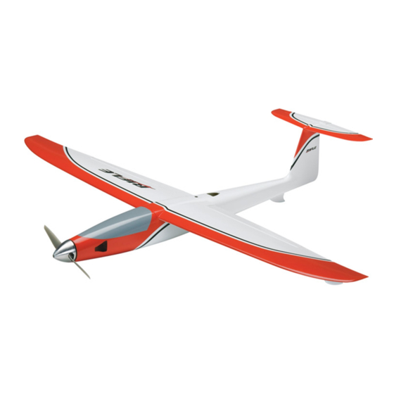
INSTRUCTION MANUAL
SPECIFICATIONS
Wingspan: 31 in [785mm]
2
Wing Area: 112 in
Wing Loading: 21.9–23.1 oz/ft
Length: 24.5 in [620mm]
WARRANTY
Great Planes
®
Model Manufacturing Co. guarantees this kit to
be free from defects in both material and workmanship at the
date of purchase. This warranty does not cover any component
parts damaged by use or modification. In no case shall Great
Planes' liability exceed the original cost of the purchased kit.
Further, Great Planes reserves the right to change or modify this
warranty without notice.
In that Great Planes has no control over the final assembly or
material used for final assembly, no liability shall be assumed nor
accepted for any damage resulting from the use by the user of
the final user-assembled product. By the act of using the
user-assembled product, the user accepts all resulting liability.
If the buyer is not prepared to accept the liability associated
with the use of this product, the buyer is advised to return
READ THROUGH THIS MANUAL BEFORE STARTING CONSTRUCTION. IT CONTAINS IMPORTANT
INSTRUCTIONS AND WARNINGS CONCERNING THE ASSEMBLY AND USE OF THIS MODEL.
Entire Contents © 2010
2
[7.2 dm
]
2
2
[67–70 g /dm
]
Weight: 17–18 oz [480–510 g]
Radio: 3-channel, 2 nano servos, mini receiver
Motor, ESC, Battery: 24-33-3180kV Ammo inrunner,
25A ESC, 1500mAh 11.1V 25C LiPo
this kit immediately in new and unused condition to the
place of purchase.
To make a warranty claim send the defective part or item to
Hobby Services at the address below:
3002 N. Apollo Dr. Suite 1
Champaign IL 61822 USA
Include a letter stating your name, return shipping address, as
much contact information as possible (daytime telephone
number, fax number, e-mail address), a detailed description of
the problem and a photocopy of the purchase receipt. Upon
receipt of the package the problem will be evaluated as quickly
as possible.
airsupport@greatplanes.com
Hobby Services
Champaign, Illinois
(217) 398-8970, Ext 5
GPMA1805 Mnl
Advertisement
Table of Contents

Subscribe to Our Youtube Channel
Related Manuals for GREAT PLANES Electrifly Rifle


Summary of Contents for GREAT PLANES Electrifly Rifle
-
Page 1: Instruction Manual
3002 N. Apollo Dr. Suite 1 Champaign IL 61822 USA In that Great Planes has no control over the final assembly or material used for final assembly, no liability shall be assumed nor Include a letter stating your name, return shipping address, as... -
Page 2: Table Of Contents
AMA ........2 the Rifl e visit the Great Planes web site at www.greatplanes. -
Page 3: Decisions You Must Make
Never blow into a part to remove fi berglass dust, as the The: dust will blow back into your eyes. Always wear safety ❍ Great Planes ElectriFly SS-25 25 Amp goggles, a particle mask and rubber gloves when grinding, drilling and sanding fi berglass parts. Vacuum... -
Page 4: Additional Items Required
A suitable power contact Product Support. When reporting defective or supply then for the PolyCharge4 is the Great Planes 12V missing parts, use the part names exactly as they are written 12A DC power supply (GPMP0901). -
Page 5: Ordering Replacement Parts
List that follows. The fastest, most economical service can be provided by your hobby dealer or mail-order company. To locate a hobby dealer, visit the Great Planes web site at www.greatplanes.com. Select “Where to Buy” in the menu across the top of the page and follow the instructions provided to locate a U.S., Canadian or International dealer. - Page 6 the tab in the back of the mount into the former and holding Cut off the unused arms down the front with one of the 2mm x 10mm Phillips wood screws included with this kit. 5/16" [8mm] ELEVATOR Servo Arm ❏...
-
Page 7: Install The Motor
tightening the screws, make certain they are getting a good to thoroughly “rub” the strip down onto the bottom of the “bite” into the fi n and that they can be tightened securely. fuselage. Apply a few drops of thin CA around the edges of You may be tempted to permanently glue the stab into the strip to make sure it never comes up. -
Page 8: Mount The Receiver
❏ 5. Apply double-sided foam adhesive mounting tape or Mount the Receiver the adhesive hook & loop material to the ESC so it can be mounted inside the top of the fuselage. ❏ 6. Drop the motor and ESC down into the fuselage so the motor shaft comes out the hole in the middle of the motor mount. -
Page 9: Mark The Balance Range
also used Shoe Goo to glue the ESC wire to the side of the Hook Up the Ailerons fuselage so it wouldn’t get in the way of the battery or aileron servo. Other, non-permanent adhesive such as RTV silicone would also be suitable for this. Mark the Balance Range ❏... -
Page 10: Mount The Landing Skids
9/16" Mount the Landing Skids [15 mm] Don’t fl y your Rifl e without the landing skids. In addition to protecting the underside, the landing skids perform the important function of causing the plane to maintain a straight-ahead trajectory on landing. Otherwise, it may spin and pirouette, causing one of the wing tips to dig into the ground and possibly cause damage. -
Page 11: Apply The Decals
1. Use scissors or a sharp hobby knife to cut each decal from the sheet. 2. Be certain the model is clean and free from oily fi ngerprints and dust. Peel the fi rst decal you wish to apply from its protective backing. -
Page 12: Balance The Model (C.g.)
❏ compare the up and down throw to the specifi ed throw below. 2. At this stage your Rifl e should be in ready-to-fl y If necessary, adjust the elevator throw by changing the ATVs condition with all of the components in place including the in your transmitter or by moving the pushrod on the servo arm. -
Page 13: Balance The Model Laterally
5. To fi nd out how much weight will be required, lay AMA SAFETY CODE ( EXCERPTS segments of Great Planes “stick-on” lead (GPMQ4485) on the fuselage over the nose or tail where it will be attached. Nose weight can be added inside the top of the fuselage just... -
Page 14: Check List
When the Rifle is flying in front of you… CHECK LIST it’s easy to see! During the last few moments of preparation your mind may be elsewhere anticipating the excitement of the fi rst fl ight. Because of this, you may be more likely to overlook certain checks and procedures that should be performed before the model is fl... -
Page 15: Ground Check And Range Check
direction. Then, arm the motor and run it up for a second Ground Check and Range Check to make sure it is making full power and sounds good. Make sure your launch will be directly into any prevailing wind. Inform your assistant of your intentions, make certain he Always perform an operational ground check of your radio acknowledges, and then apply full throttle. -
Page 16: Landing
Once over the flying field the Rifle prefers a long, shallow descent. LONG SHALLOW After a few fl ights you’ll have your Rifl e all trimmed out Landing for level fl ight and be executing perfect hand-launches, adrenaline-pumping fl ights and smooth, routine landings The Rifl...
Need help?
Do you have a question about the Electrifly Rifle and is the answer not in the manual?
Questions and answers