Table of Contents
Advertisement
Quick Links
Download this manual
See also:
Instruction Manual
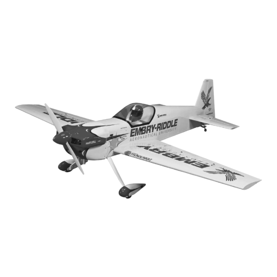
Giant Scale 85 –100 cc Aerobatic/3D ARF
SPECIFICATIONS
Wingspan:
100 in
[2540mm]
Wing Area:
1892 sq in
[122 dm
WARRANTY
Great Planes
Model Manufacturing Co. guarantees this kit to
®
be free from defects in both material and workmanship at the
date of purchase. This warranty does not cover any component
parts damaged by use or modification. In no case shall Great
Planes' liability exceed the original cost of the purchased kit.
Further, Great Planes reserves the right to change or modify this
warranty without notice.
In that Great Planes has no control over the final assembly or
material used for final assembly, no liability shall be assumed nor
accepted for any damage resulting from the use by the user of
the final user-assembled product. By the act of using the
user-assembled product, the user accepts all resulting liability.
If the buyer is not prepared to accept the liability associated
with the use of this product, the buyer is advised to return
READ THROUGH THIS MANUAL BEFORE STARTING CONSTRUCTION. IT CONTAINS IMPORTANT
INSTRUCTIONS AND WARNINGS CONCERNING THE ASSEMBLY AND USE OF THIS MODEL.
Entire Contents © Copyright 2009
Weight:
Wing
Loading:
2
]
24 – 28 lb
[10880-12700 g]
29– 34 oz/ ft
2
[88– 104 g /dm
2
]
this kit immediately in new and unused condition to the
place of purchase.
To make a warranty claim send the defective part or item to
Hobby Services at the address below:
Include a letter stating your name, return shipping address, as
much contact information as possible (daytime telephone
number, fax number, e-mail address), a detailed description of
the problem and a photocopy of the purchase receipt. Upon
receipt of the package the problem will be evaluated as quickly
as possible.
Length:
96 in
[2440mm]
Radio:
4-5 channel with
9 standard size servos
Engine:
85 – 100cc gasoline
Hobby Services
3002 N. Apollo Dr. Suite 1
Champaign IL 61822 USA
Champaign, Illinois
(217) 398-8970, Ext 5
airsupport@greatplanes.com
GPMA1285 Mnl 2.0
Advertisement
Table of Contents

Related Manuals for GREAT PLANES Eagle 580


Summary of Contents for GREAT PLANES Eagle 580
-
Page 1: Specifications
READ THROUGH THIS MANUAL BEFORE STARTING CONSTRUCTION. IT CONTAINS IMPORTANT INSTRUCTIONS AND WARNINGS CONCERNING THE ASSEMBLY AND USE OF THIS MODEL. Champaign, Illinois (217) 398-8970, Ext 5 airsupport@greatplanes.com Entire Contents © Copyright 2009 GPMA1285 Mnl 2.0... -
Page 2: Table Of Contents
DECISIONS YOU MUST MAKE . . . . . . . . . . . . . . . . . . . . . 3 Matt Chapman Eagle 580 ARF . If there is new technical Radio Equipment . -
Page 3: Safety Precautions
. 1 . Your Great Planes Giant Matt Chapman Eagle 580 ARF should not be considered a toy, but rather a sophisticated, working model that functions very much like a full-size Remember: Take your time and follow the instructions to end airplane . -
Page 4: Engine Recommendations
The recommended engine size range for the Great Planes • Pro 6-minute epoxy (GPMR6045) Giant Matt Chapman Eagle 580 ARF is 85 – 100cc . This • Threadlocker thread locking cement (threadlocker) manual will detail the installation of the DA-100 engine with (GPMR6060) twin canister style exhaust . -
Page 5: Important Building Notes
Replacement parts for the Great Planes Giant Matt Chapman your experience to decide what type of glue to use . When Eagle 580 ARF are available using the order numbers in a specific type of adhesive works best for that step, the the Replacement Parts List that follows . -
Page 6: Kit Contents
KIT CONTENTS 1 . Cowl 5 . Main Gear 9 . Stab Tubes 2 . Fuselage 6 . Wheels 10 . Rudder 3 . Canopy/Hatch 7 . Wheel Pants 11 . Wings and Ailerons 4 . Aluminum Spinner 8 . Stab and Elevators 12 . -
Page 7: Mount The Elevator Servos
3 . Attach a 40" [1016mm] heavy duty servo lead extension and secure it using 3/8" [9 .5mm] diameter heat shrink tubing . 3 . Attach the ball link to the outer tapped hole of one of the one-sided servo arms with 4-40 x 1/2" [13mm] Socket Head Cap Screw [SHCS] brass stand off and 4-40 lock nut . -
Page 8: Assemble The Wing
11 . Plug the servo into the receiver and turn the radio on . 12 . Place the appropriate servo arm adapter on the servo . The inserts have letters stamped on the bottom of them (A=Airtronics/JR, F=Futaba, H=Hitec) . 7 . -
Page 9: Assemble The Fuse
ASSEMBLE THE FUSE Install the Tail Gear 3 . Use the string in the wing to route each servo lead through the wing . Mount the servos, noting that the servo arms go toward the trailing edge of the wing . 1 . -
Page 10: Attach The Rudder
Attach the Rudder 1 . Mount the rudder control horns as shown, using the 4 . Coat the hinge barbs with glue . remaining uncut 4" [102mm] bolt . 2 . Prepare the five hinges by cleaning the barbs with denatured alcohol and applying household oil or petroleum jelly to the hinge pins . -
Page 11: Install The Rudder Servos
3 . Using silver solder, flux and your hobby torch, solder an unthreaded steel clevis onto the unthreaded end of each pushrod so that 1/4" [6 .4mm] of rod protrudes past the barrel of the clevis . Wipe away the remaining flux with a damp cloth 6 . - Page 12 6 . Cut the supplied steel pull-pull cable in half . Swage a threaded coupler to one side of each of the two cables . Note: 9 . Turn on your radio and fit the servo arms to the rudder The swage must be crimped tightly! Inspect each swage for servos .
-
Page 13: Install The Main Landing Gear
3 . Mount the wheel pant with two 8-32 x 3/4" [19mm] SHCS . Center the wheel in the wheel pant and tighten the wheel collars . 12 . Tension and adjust the cables at the couplers by removing the control horn pivot pin and tightening or loosening the pivot on the coupler . -
Page 14: Mount The Engine
Mount the Engine We have made provisions to mount either the DA-85 or the DA-100 gas engine from Desert Aircraft . This section of the manual will guide you in installing the DA-100 along with the optional short canister-style exhaust . Laser-etched marks have been made on the firewall that match the mounting pattern of the DA-100 . -
Page 15: Assemble And Install The Fuel Tank
[6 .4mm] lock washers . You’ll want to inspect these screws after the first few flights and then periodically after that to make sure that they’re still tight . 2mm & 3mm Thicknesses Use the next four steps to mount a DA-85 engine . Notched Ply Spacers (Allow carb... -
Page 16: Install The Throttle & Choke Servos
2 . Solder the brass barbs to the ends of the brass tubes . Note: Get the tubes just hot enough for the solder to flow . If you get the tubes too hot it will damage the tank stopper . 6 . - Page 17 3 . Assemble the throttle and choke servo tray as shown . Note: Two triangle support pieces are supplied to support the tray . Please glue these in later after you have installed the tray in the fuse . 6 . Lightly sand the outside of the 36" [914mm] throttle outer pushrod tube .
-
Page 18: Install The Canister Mufflers (Da-100 Only)
Install the Canister Mufflers (DA-100 only) This section covers the installation of the optional MTW short canister exhaust system for the DA-100 . This airplane was designed around this particular system, but other short canisters may fit . As is, the model will accommodate twin 70mm diameter cans whose can lengths are no longer than 250mm . -
Page 19: Install The Radio & Ignition Equipment
Install the Radio & Ignition Equipment 3 . Position the exhaust header over the right cylinder’s exhaust port and mark the pipe about 1-1/4" [32mm] forward of the firewall face . Use a felt tip pen to label this as the right hand pipe . -
Page 20: Mount The Cowl
7 . Install the fill line plug . Mount the Cowl 4 . Secure your battery leads with 3/8" [9 .5mm] heat shrink tubing . 1 . Apply a 6" [152mm] piece of masking tape over each of the six pre-installed blind nuts for the cowl . Each piece of tape should extend straight back and be parallel with the 5 . - Page 21 3 . Slide the cowl over the engine onto the fuselage . On the DA-100 you need to remove one of the two spark plug boots to get the cowl on . 7 . Drill a 1/8" [3 .2mm] hole at each mark and reinstall the cowl using six 4-40 x 1/2"...
-
Page 22: Final Assembly
FINAL ASSEMBLY Mount the Stabilizers The removable tail needs to be checked often for wear . If the tail develops excessive movement, thin CA sparingly applied to the inside of the stab tubes and root ribs will cure it . If you are able to transport the Eagle with the stabs installed, we recommend permanently attaching the stab to the fuse with epoxy . -
Page 23: Attach The Canopy
Great Planes Check the Control Directions Giant Matt Chapman Eagle 580 ARF flies, you would like to change the throws to suit your taste, that is fine . However, too much control throw could make the model 1 . - Page 24 1 . Please read and understand the Proper Pushrod Hookup illustrations and guidelines on page 25 . 2 . Measure and set the control throws according to the chart below . NOTE: The throws are measured at the widest part of the elevators, rudder and ailerons .
-
Page 25: Proper Pushrod Hookup
Proper Pushrod Hookup Avoid ing Flu tt e r, M aximiz ing S e rvo O u t pu t To rqu e Note: Your control horn may vary. When connecting pushrods and setting up your control CONTROL throws, critically SERVO ARM Pivot point HORN OFFSET... -
Page 26: Balance The Model (C.g.)
nose to balance . If the nose drops, the model is “nose heavy” Balance the Model (C.G.) and the battery pack must be shifted aft or weight must be added to the tail to balance . More than any other factor, the C .G . (balance point) can 4 . -
Page 27: Identify Your Model
Identify Your Model Range Check No matter if you fly at an AMA sanctioned R/C club site or Ground check the operational range of your radio before the if you fly somewhere on your own, you should always have first flight of the day . With the transmitter antenna collapsed your name, address, telephone number and AMA number on and the receiver and transmitter on, you should be able to or inside your model . -
Page 28: Ama Safety Code (Excerpts)
GASOLINE ENGINES CAN START BY A SIMPLE FLIP OF 9) Under no circumstances may a pilot or other person touch THE PROP, REGARDLESS IF THE MODEL’S RECEIVER a powered model in flight; nor should any part of the model other than the landing gear, intentionally touch SWITCH IS ON! ALWAYS UTILIZE AN IGNITION SWITCH the ground, except while landing. -
Page 29: Flying
14 . Secure the pressure tap (if used) to the muffler with Takeoff high temp RTV silicone, thread locking compound or J .B . Weld . Before you get ready to takeoff, see how the model handles 15 . Make sure the fuel lines are connected and are not on the ground by doing a few practice runs at low speeds kinked . - Page 30 (into the wind) keeping the nose down to maintain airspeed the model behaves in certain conditions (such as on high and control . Level the attitude when the model reaches the or low rates) . This is not necessarily to improve your skills runway threshold, modulating the throttle as necessary to (though it is never a bad idea!), but more importantly so maintain your glide path and airspeed .
Need help?
Do you have a question about the Eagle 580 and is the answer not in the manual?
Questions and answers