Table of Contents
Advertisement
Quick Links
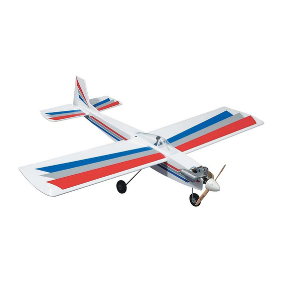
Length: 50" [1270mm]
Wingspan: 58.75" [1492mm]
Wing Loading: 17.1 - 20.2 oz/sq ft [52.2 - 61.6 g/sq cm]
Radio: 4-ch (4 servos)
Engine: .40 - .51 two-stroke [6.5 - 8.4cc 2-stroke]
Great Planes Model Manufacturing Co. guarantees this kit to be free from defects in both material and
workmanship at the date of purchase. This warranty does not cover any component parts damaged by use or
modification. In no case shall Great Planes' liability exceed the original cost of the purchased kit. Further, Great
Planes reserves the right to change or modify this warranty without notice.
In that Great Planes has no control over the final assembly or material used for final assembly, no liability shall be
assumed nor accepted for any damage resulting from the use by the user of the final user-assembled product. By the
act of using the user-assembled product, the user accepts all resulting liability.
If the buyers are not prepared to accept the liability associated with the use of this product, they are advised
to return this kit immediately in new and unused condition to the place of purchase.
READ THROUGH THIS INSTRUCTION MANUAL
FIRST. IT CONTAINS IMPORTANT INSTRUCTIONS
AND WARNINGS CONCERNING THE ASSEMBLY
AND USE OF THIS MODEL.
ES03 V2.0
Weight: 5.5 - 6.5 lbs [2495 - 2948g]
Wing Area: 742 sq in [ 47.9sq cm]
.52 - .70 four-stroke [8.5 - 11.5cc 4-stroke]
INSTRUCTION MANUAL
TM
WARRANTY
1610 Interstate Drive, Champaign, IL 61822
(217) 398-8970, Ext 2
airsupport@greatplanes.com
Entire Contents © Copyright 2002
Advertisement
Table of Contents

Related Manuals for GREAT PLANES Easy Sport 40


Summary of Contents for GREAT PLANES Easy Sport 40
- Page 1 Planes reserves the right to change or modify this warranty without notice. In that Great Planes has no control over the final assembly or material used for final assembly, no liability shall be assumed nor accepted for any damage resulting from the use by the user of the final user-assembled product. By the act of using the user-assembled product, the user accepts all resulting liability.
-
Page 2: Table Of Contents
Optional Supplies and Tools ..... . up balsa airplanes. The Easy Sport 40 ARF will provide an IMPORTANT BUILDING NOTES .... -
Page 3: Decisions You Must Make
The Easy Sport 40 ARF will fly well with any of the representations are expressed or implied as to the recommended engine sizes. For “Hot Dogging” and performance or safety of your completed model. -
Page 4: Adhesives And Building Supplies
There are two types of screws used in this kit: this is the “short list” of the most important items required to build the Easy Sport 40 ARF. Great Planes Pro™ CA and Sheet metal screws are designated by a number and a length. - Page 5 Product Support. When reporting defective or missing parts, use the part names exactly as they are written in the Kit Contents list on this page. Great Planes Product Support: Telephone: (217) 398-8970 Fax: (217) 398-7721 E-mail: airsupport@greatplanes.com...
-
Page 6: Wing Assembly
WING ASSEMBLY Assemble the Wing Joiners Note: As epoxy is used for most of this kit’s assembly, it’s a good idea to keep rubbing alcohol and paper towels handy for cleanup. Before the epoxy has had time to cure, moisten a paper towel with alcohol and clean off any excess epoxy. -
Page 7: Install The Aileron Servo Tray
❏ 2. Glue the wing bolt plate in position with 6-minute Install the Aileron Servo Tray epoxy or medium CA. ❏ 1. Lay the 1/8” [3.2mm] ply aileron servo tray on the ❏ bottom of the wing. Center the tray over its mounting area 3. -
Page 8: Install The Pushrod Tubes
Install the Pushrod Tubes ❏ 3. Fit the two halves of the engine mount together. Use ❏ four #6 flat washers and four 6-32 x 1" [25.4mm] phillips 1. Locate the pushrod exit slot under the covering on the head screws to attach the engine mount to the firewall. tail section of the fuselage by lightly pressing with your Blind nuts have already been installed in the firewall for this fingers. -
Page 9: Assemble The Fuel Tank
Assemble the Fuel Tank ❏ 4. Push the stopper assembly into the tank and check the fit of the parts. The end of the bent tube should just touch the top of the tank. Rotate the tank around with the ❏... - Page 10 ❏ 5. Install fuel lines from the fuel outlet on the tank to the engine and from the vent outlet on the tank to the muffler. ❏ 2. Install the fuel tank in the fuselage. The front of the Note: The photo shows an O.S. .40 LA engine with a tank fits into the cutout in the firewall.
-
Page 11: Install The Tail Components
INSTALL THE TAIL COMPONENTS Join the Elevator Halves ❏ 4. Use a straightedge to align the elevator halves on a flat surface. Using 6-minute epoxy, glue the joiner wire into position. Make sure the joiner wire is fully seated in the elevator halves before the epoxy cures. - Page 12 ❏ ❏ 3. Measure and mark an accurate centerline on the top 6. With the stabilizer properly aligned, use a felt-tip pen of the horizontal stabilizer. Make sure to mark the to trace a line around the tail of the airplane on the top and centerline on the trailing edge also.
-
Page 13: Install The Vertical Fin
Install the Vertical Fin Install the Hinges ❏ 1. Remove the rudder from the vertical fin. Test fit the vertical fin in the slot in the top of the fuselage. Sand the edges of the slot if necessary to obtain a snug fit. Draw a ❏... -
Page 14: Install The Landing Gear
hinge. Turn the fuselage over and apply six more drops of thin INSTALL THE LANDING GEAR CA to the other side of each hinge. DO NOT use accelerator while hinging, as the CA must wick into the hinge to properly attach the hinges. -
Page 15: Mount The Nose Gear
❏ 6. Using the holes in the front of the straps as a guide, drill a 1/16" [1.6mm] hole for the front screws. ❏ 2. Slide the steering arm into contact with the bottom of the engine mount. Rotate the gear wire so that the axle is parallel to the firewall. -
Page 16: Install The Pushrods & Control Horns
❏ ❏ 2. Following the manufacturer’s recommendations, 5. Thread a nylon clevis 13 revolutions onto the install and connect three servos, the receiver, the switch threaded end of both 6” [152mm] wire pushrods. Install a and the battery as shown in the photo. We added a Great silicone retainer onto each clevis. - Page 17 ❏ ❏ 4. Center the elevator, then mark the pushrod where it crosses the servo horn hole. Enlarge the servo horn hole with a 5/64" [2mm] drill bit. Make a 90 degree bend in the pushrod on the mark. Cut off the excess wire 3/8" [9.5mm] RIGHT WRONG below the bend.
-
Page 18: Final Assembly
Magnetic Prop Balancer (TOPQ5700) in the workshop ❏ 9. Turn the radio on. Check that the rudder trim is and keep a Great Planes Finger tip Balancer centered. Align the nose wheel axle with the firewall by (GPMQ5000) in our flight box. -
Page 19: Install The Wheels
this time by painting and adding a pilot figure to suit your Install the Wheels own personal tastes. Roughen the bottom of the canopy edge, as well as the area on the wing fairing that the canopy contacts. Be careful not to scratch any areas that may be visible when the canopy is installed. -
Page 20: Preflight
Tail weight may be added by using Inspect your radio installation and confirm that all the control Great Planes (GPMQ4485) “stick-on” lead weights. Later, if surfaces respond correctly to transmitter inputs. The engine the balance proves to be O.K., you can open the bottom of operation must also be checked by confirming that the engine the fuse and glue these permanently in position. -
Page 21: Engine Safety Precautions
The Great Planes Easy Spor t is a great flying spor t previous crash. airplane that flies smoothly and predictably, yet is highly maneuverable. -
Page 22: Flight
Flight We recommend that you take it easy with your Easy Sport for the first several flights and gradually “get acquainted” with this fantastic airplane as your engine gets fully broken- in. Add and practice one maneuver at a time, learning how she behaves in each one. - Page 23 –AIRCRAFT– 1996 OFFICIAL AMA NATIONAL MODEL AIRCRAFT SAFETY CODE Effective January 1, 1996 Model Flying MUST be in accordance with this Code in order for models, smoke bombs, all explosive gases (such as hydrogen- AMA Liability Protection to apply. filled balloons), ground mounted devices launching a projectile. The only exceptions permitted are rockets flown in accordance with the National Model Rocketr y Safety Code or those GENERAL...
- Page 24 FLIGHT LOG DATE COMMENTS Started Construction Finished Construction First Flight...
Need help?
Do you have a question about the Easy Sport 40 and is the answer not in the manual?
Questions and answers