Table of Contents
Advertisement
Quick Links
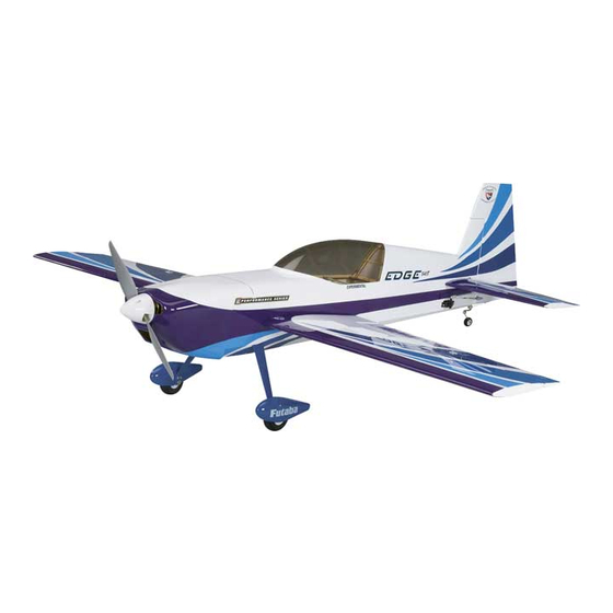
Wingspan: 49.5 in [1260mm]
2
2
Wing Area: 490 in
[31.6dm
]
Weight: 3.25 – 3.5 lb [1470 – 1590g]
Wing Loading: 15.0 – 16.0 oz/ft
2
Length: 48 in [1220mm]
Radio:
4-channel minimum, 5-channel computer radio with
mixing capabilities (for separate ailerons)
™
Motor:
RimFire
42-50-800 out-runner
Great Planes
®
Model Manufacturing Co. guarantees this kit to be
free from defects in both material and workmanship at the date
of purchase. This warranty does not cover any component parts
damaged by use or modifi cation. In no case shall Great Planes'
liability exceed the original cost of the purchased kit. Further,
Great Planes reserves the right to change or modify this warranty
without notice.
In that Great Planes has no control over the fi nal assembly or
material used for fi nal assembly, no liability shall be assumed nor
accepted for any damage resulting from the use by the user of
the fi nal user-assembled product. By the act of using the user-
assembled product, the user accepts all resulting liability.
If the buyer is not prepared to accept the liability associated
with the use of this product, the buyer is advised to return this
kit immediately in new and unused condition to the place of
purchase.
READ THROUGH THIS MANUAL BEFORE STARTING CONSTRUCTION. IT CONTAINS IMPORTANT INSTRUCTIONS
AND WARNINGS CONCERNING THE ASSEMBLY AND USE OF THIS MODEL.
Entire Contents © Copyright 2008
INSTRUCTION MANUAL
[46 – 49g/dm
2
]
WARRANTY
To make a warranty claim send the defective part or item to Hobby
Services at the address below:
3002 N. Apollo Dr., Suite 1
Champaign, IL 61822 USA
Include a letter stating your name, return shipping address, as
much contact information as possible (daytime telephone number,
fax number, e-mail address), a detailed description of the problem
and a photocopy of the purchase receipt. Upon receipt of the
package the problem will be evaluated as quickly as possible.
airsupport@greatplanes.com
Hobby Services
Champaign, Illinois
(217) 398-8970, Ext 5
GPMA1572MNL V1.0
Advertisement
Table of Contents

Related Manuals for GREAT PLANES EDGE 540 T Performance Series


Summary of Contents for GREAT PLANES EDGE 540 T Performance Series
-
Page 1: Instruction Manual
This warranty does not cover any component parts damaged by use or modifi cation. In no case shall Great Planes’ Hobby Services liability exceed the original cost of the purchased kit. Further, 3002 N. Apollo Dr., Suite 1... -
Page 2: Table Of Contents
TABLE OF CONTENTS INTRODUCTION INTRODUCTION ............... 2 The full-scale Zivko Edge 540T is a great two seat, competition AMA .................. 2 aerobatic trainer. Great Planes has taken the best qualities of SAFETY PRECAUTIONS ..........3 the full-scale Edge 540T and reduced it down to a lightweight, DECISIONS YOU MUST MAKE ........ -
Page 3: Safety Precautions
PROTECT YOUR MODEL, YOURSELF DECISIONS YOU MUST MAKE & OTHERS..FOLLOW THESE IMPORTANT SAFETY PRECAUTIONS This is a partial list of items required to fi nish the Edge 540T EP ARF that may require planning or decision making before starting to build. 1. -
Page 4: Motor Recommendations
❏ APC 12" x 6E Propeller (APCQ4130) Motor Recommendations ❏ ElectriFly Voltage Regulator (GPMM1920) ❏ Great Planes Parallel ESC Adapter Deans Ultra Connector (GPMM3141) The Edge 540T EP ARF comes with a mounting box for the Great Planes RimFire ™ brushless out-runner motor. -
Page 5: Ordering Replacement Parts
International dealer. This is a 4-40 SHCS that is 3/4" [19mm] long with forty threads per inch. Parts may also be ordered directly from Hobby Services by calling (217) 398-0007, or via facsimile at (217) 398-7721, • When you see the term test fi t in the instructions, but full retail prices and shipping and handling charges will it means that you should fi... -
Page 6: Kit Inspection
KIT INSPECTION KIT INSPECTION Before starting to build, take an inventory of this kit to make sure it is complete and inspect the parts to make sure they are of acceptable quality. If any parts are missing or are not of acceptable quality, or if you need assistance with assembly, contact Product Support. -
Page 7: Preparations
PREPARATIONS ❏ 1. If you have not done so already, remove the major parts of the kit from the box and inspect for damage. If any parts are damaged or missing, contact Product Support at the address or telephone number listed in the “Kit Inspection” section on page 6. -
Page 8: Install The Aileron Servo & Pushrods
pushrod where it crosses the aileron servo arm. Make a 90° HINGE LINE bend at the mark. Cut the pushrod 3/8" [9.5mm] past the bend. Attach the pushrod to the aileron servo arm with a nylon FasLink. CORRECT INCORRECT ❏ ❏ 9. -
Page 9: Install The Main Landing Gear
location where the set screw tightens on the axle and use a metal cutting fi le to fi le a fl at spot on the axle. Apply a drop of threadlocker on the set screw and reinstall the wheel collar on the axle. -
Page 10: Install The Tail Gear
nylon tail gear post onto the thin tail gear wire. Insert the tail gear wire through the aluminum tail gear bracket and wheel collar while inserting the tail gear post in the bottom of the rudder. Tighten the set screw in the wheel collar and glue the tail gear post in the rudder with thin CA. -
Page 11: Install The Stabilizer
30-minute epoxy to the wood, top and bottom. Slide the stab through the fuselage so that approximately 1/2" [12.7mm] of bare wood is showing on the other side and apply epoxy to the wood. Now align the stab, remove the masking tape and wipe off any excess epoxy from the stab and fuselage. -
Page 12: Install The Elevators Hinges
❏ ❏ 4. Test fi t the elevators to the stab with the hinges. If the hinges don’t remain centered, stick a pin through the middle ❏ 1. Install the RimFire motor using four 4-40 x 1/2" [12.7mm] of the hinge to hold it in position. SHCS, four 3mm lock washers and four 3mm fl... -
Page 13: Install The Rudder Servo
❏ 2. Install a 16" [406mm] servo extension to the elevator servo. Secure the extension to the lead with tape, a piece of heat-shrink tubing some other method to keep them from coming unplugged. ❏ 5. Slide a silicone clevis retainer over the clevis. With the elevator servo and the elevator centered, mark the elevator pushrod where it crosses the elevator servo arm. - Page 14 ❏ ❏ 2. Cut the covering from over the two pull-pull exits at the 5. Insert the 2mm threaded rudder control horn rod. Center aft end of the two servo openings, between the openings. the rod in the rudder with two 2mm fl at washers and 2mm nuts on each side.
-
Page 15: Rudder Servo Installation In The Tail
Rudder Servo Installation in the Tail ❏ 8. Working from the end of the string inside the fuselage, pass the string through a crimp, through the rigging coupler and back through the crimp. Squeeze the crimp with a pliers to secure the string in the crimp. Apply a drop of thin CA to ❏... -
Page 16: Apply The Decals
When positioned properly the control horn will rest on a through the slot in the battery tray, under the tray and back hardwood plate in the rudder. The center of the control horn through the slot on the other side of the tray. is approximately 5/8"... -
Page 17: Set The Control Throws
These are the recommended control surface throws: HIGH RATE ELEVATOR: 3/4" [19mm], 12° up 3/4" [19mm], 12° down RUDDER: 3-1/2" [89mm], 30° left 3-1/2" [89mm], 30° right AILERONS: 3/4" [19mm], 15° up 3/4" [19mm], 15° down LOW RATE ELEVATOR: 1/2" [13mm], 8° up 1/2"... -
Page 18: Finish The Model
❏ 1. Use a felt-tip pen or 1/8" [3mm]-wide tape to accurately FINISH THE MODEL mark the C.G. on the top of the wing at the side of the fuselage. The C.G. is located 2-13/16" [71mm] back from the leading edge of the wing at the side of the fuselage. This is where your model should balance for the fi... -
Page 19: Balance The Model Laterally
Balance the Model Laterally Balance Propellers ❏ 1. With the wing level, have an assistant help you lift the model by the motor propeller shaft and the bottom of the fuselage under the TE of the fi n. Do this several times. ❏... -
Page 20: Ama Safety Code (Excerpts)
Do not run the motor in an area of loose gravel or sand; the Radio Control propeller may throw such material in your face or eyes. Keep your face and body as well as all spectators away from 1) I will have completed a successful radio equipment ground the plane of rotation of the propeller as you run the motor. -
Page 21: Flying
❏ 8. Reinforce holes for wood screws with thin CA where Takeoff appropriate (servo mounting screws, control horn screws, etc.). ❏ 9. Confi rm that all controls operate in the correct direction Before you get ready to takeoff, see how the model handles and the throws are set up according to the manual. -
Page 22: Landing
capable of just about every aerobatic maneuver you can do. Become familiar with the high and low rate settings before using the 3D rates. If you have not fl own an airplane with 3D rates you should work your way into these higher 3D rates cautiously. - Page 23 UPRIGHT FLAT SPINS TORQUE ROLL Pull the nose up slightly and slowly decrease power. As the This is the same as the vertical hover but without the use of model slows to a few mph, slowly apply full left rudder and right aileron to keep the model from rolling.
- Page 24 turn the model, simply input the elevator or rudder a little sooner or later in the rotation. It’s all a matter of timing. PINWHEEL ElectriFly Silver Series 45A Brushless ESC With Silver Series brushless ESCs, the only way their performance would be any easier to enjoy is if they came already installed.
Need help?
Do you have a question about the EDGE 540 T Performance Series and is the answer not in the manual?
Questions and answers