Table of Contents
Advertisement
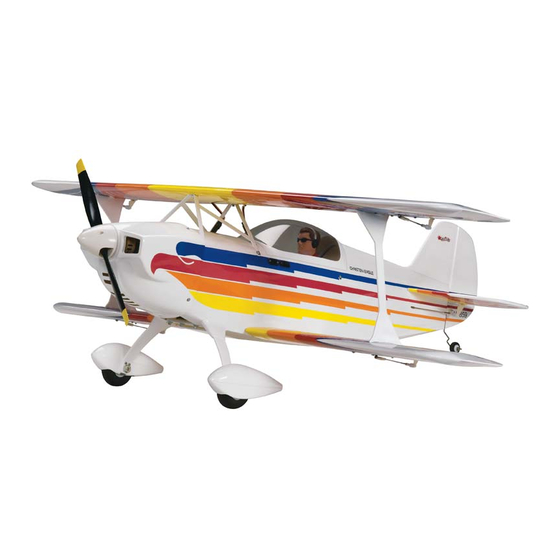
INSTRUCTION MANUAL
INSTRUCTION MANUAL
SPECIFICATIONS
SPECIFICATIONS
Wingspan:
Top: 42.5 in [1080mm]
Bottom: 40 in [1015mm]
Wing Area:
2
441 in
[28.4 dm
WARRANTY
Great Planes
®
Model Manufacturing Co. guarantees this kit to
be free from defects in both material and workmanship at the
date of purchase. This warranty does not cover any component
parts damaged by use or modification. In no case shall Great
Planes' liability exceed the original cost of the purchased kit.
Further, Great Planes reserves the right to change or modify this
warranty without notice.
In that Great Planes has no control over the final assembly or
material used for final assembly, no liability shall be assumed nor
accepted for any damage resulting from the use by the user of
the final user-assembled product. By the act of using the
user-assembled product, the user accepts all resulting liability.
If the buyer is not prepared to accept the liability associated
with the use of this product, the buyer is advised to return
READ THROUGH THIS MANUAL BEFORE STARTING CONSTRUCTION. IT CONTAINS IMPORTANT
INSTRUCTIONS AND WARNINGS CONCERNING THE ASSEMBLY AND USE OF THIS MODEL.
© 2011 Hobbico
®
, Inc.
Weight:
Wing
Loading:
2
]
.46 – .72/EP ARF
.46 – .72/EP ARF
The Christen Eagle name is used by Hobbico
The Christen Eagle name is used by Hobbico
Length:
Length:
Radio:
Radio:
5.75– 6.25 lb
Engine:
[2610– 2830 g]
30– 33 oz/ft
2
2
[92 – 101 g /dm
]
this kit immediately in new and unused condition to the
place of purchase.
To make a warranty claim send the defective part or item to
Hobby Services at the address below:
3002 N. Apollo Dr. Suite 1
Champaign IL 61822 USA
Include a letter stating your name, return shipping address, as
much contact information as possible (daytime telephone
number, fax number, e-mail address), a detailed description of
the problem and a photocopy of the purchase receipt. Upon
receipt of the package the problem will be evaluated as quickly
as possible.
airsupport@greatplanes.com
®
®
, Inc. under license from Aviat Aircraft, Inc.
, Inc. under license from Aviat Aircraft, Inc.
39.5 in
39.5 in
[1005mm]
[1005mm]
4-Channel minimum with
4-Channel minimum with
4 – 7 servos and
4 – 7 servos and
standard size receiver
standard size receiver
.46 – .55 cu in [7.5 – 9cc] two-stroke
.72 cu in [12cc] four-stroke
RimFire
™
.55 (42-60-480)
brushless outrunner motor
Hobby Services
Champaign, Illinois
(217) 398-8970, Ext 5
GPMA1431 Mnl
Advertisement
Table of Contents

Related Manuals for GREAT PLANES Christen Eagle .46


Summary of Contents for GREAT PLANES Christen Eagle .46
- Page 1 3002 N. Apollo Dr. Suite 1 Champaign IL 61822 USA In that Great Planes has no control over the final assembly or material used for final assembly, no liability shall be assumed nor Include a letter stating your name, return shipping address, as...
-
Page 2: Table Of Contents
Planes web site at greatplanes.com. Open the “Airplanes” INSTALL THE TAIL PUSHRODS AND SERVOS..14 link, then select the Christen Eagle .46 ARF. If there is new ASSEMBLE AND INSTALL THE LANDING GEAR ..15 technical information or changes to this model a “tech notice”... -
Page 3: Decisions You Must Make
Great Planes RimFire .55 (42-60-480) Outrunner Brushless (GPMG4715) If using the recommended brushless motor, a 60A brushless ESC and motor mount are required: ❏ Great Planes Silver Series 60A Brushless ESC High Volt (GPMM1850) ❏ Great Planes Brushless Motor Mount Medium (GPMG1255) -
Page 4: Propeller
This is the list of hardware and accessories required to finish ❏ Hobbico Pin Vise 1/16 Collet w/6 Bits (HCAR0696) the Christen Eagle .46 ARF. Order numbers are provided in ❏ Hobbico 8-Piece Ball Tip Hex L Wrench SAE parentheses: (HCAR0520) ❏... -
Page 5: Building Stand
The fastest, most economical service can be provided by your hobby dealer or mail-order company. To locate a hobby dealer, visit the Great Planes web site at greatplanes.com. Choose “Where to Buy” at the bottom of the menu on the left side of the page. Follow the instructions provided on the page to locate a U.S., Canadian... -
Page 6: Kit Contents
If any parts are missing or are not of acceptable quality, or if you need assistance with assembly, contact Product Support. When reporting defective or missing parts, use the part names exactly as they are written in the Kit Contents list. Great Planes Product Support: 3002 N Apollo Drive, Suite 1 Champaign, IL 61822 Telephone: (217) 398-8970, ext. -
Page 7: Preparations
PREPARATIONS ❏ 1. If you have not done so already, remove the major parts of the kit from the box and inspect for damage. If any parts are damaged or missing, contact Product Support at the address or telephone number listed in the “Kit Inspection” CUT OFF UNUSED ARMS section on the opposite page. - Page 8 into the blocks. Thread a servo mounting screw (included with the servos) into each hole and back it out. Apply a drop of thin CA to each hole to harden the wood. When the CA has dried, install the servos onto the hatch covers using the hardware supplied with the servos.
- Page 9 glue to each hole to harden the wood. When the glue has dried, install the control horns onto the ailerons using four 2-56 x 1/2" [13mm] machine screws and the control horn backplates. ❏ ❏ 10. Thread a nylon clevis 20 complete turns onto two 4"...
- Page 10 HOW TO CUT COVERING FROM BALSA Use a soldering iron to cut the covering from the area beneath the belly pan. The tip of the soldering iron doesn’t have to be sharp, but a fi ne tip does work best. Allow the iron to heat fully.
-
Page 11: Install The Tail Surfaces
INSTALL THE TAIL SURFACES ❏ 3. Measure the distance from the corners of the ailerons on the wing to the tips of the stab. Adjust the stab until the distance from the tip of the stab to the wing is equal on both ❏... - Page 12 DRILL A 5/64" [2mm] HOLE, 3/8" [9.5mm] DEEP, IN CENTER OF HINGE SLOT ❏ 5. Confi rm that the vertical fi n is square with the horizontal stab. When satisfi ed, glue it in place (even with the back of the fuselage) in the same manner.
- Page 13 ❏ ❏ 11. Test fi t the elevators to the hinges and align the outside 14. Test fi t the tail wheel wire into the hole in the rudder. edges with the edges of the stab. Make any adjustments to Test fi...
-
Page 14: Install The Tail Pushrods And Servos
INSTALL THE TAIL PUSHRODS & SERVOS ❏ 4. Trim the bottom corner from the rudder control horn. Install the control horn onto the right side of the rudder in the same manner of the elevator using two 2-56 x 1/2" [13mm] machine screws and a backplate. -
Page 15: Assemble And Install The Landing Gear
❏ ❏ 3. Slide a 5/32" [4mm] wheel collar followed by a wheel 7. Make a 90° bend at the marks on the pushrods and cut and then another wheel collar onto each axle. Mark the off the excess pushrod 1/4" [6mm] beyond the bends. Attach location of the screw holes in the wheel collars onto the axles. -
Page 16: Install The Power System
❏ ❏ 7. Mount the main landing gear to the fuselage using four 10. Install the tail wheel onto the tail wheel wire and 6-32 x 1/2" [13mm] SHCS, four #6 fl at washers, four #6 lock secure it in place with a 3/32" [2.4mm] wheel collar, 4-40 set washers and thread locking compound. - Page 17 Top of Tank Vent Fill and Carb Lines ❏ 2. Insert four 6-32 blind nuts into the back of the fi rewall. Use a 6-32 x 3/4" [19mm] SHCS and a #6 fl at washer to draw the blind nuts tight into the fi rewall. ❏...
- Page 18 ❏ 8. Install the engine mount to the fi rewall using four 6-32 x 3/4" [19mm] SHCS, four #6 fl at washers, four #6 lock washers and thread locking compound. Leave the screws slightly loose. Test fi t your engine between the mount halves. Slide the mount halves against the sides of the engine and fi...
- Page 19 ❏ 13. Cut four arms from a fi ve-armed servo arm included with your throttle servo. Center the servo with your radio ❏ system (throttle stick positioned at 50% throttle) and install 10. Attach the engine to the mount using four 6-32 x 3/4" the arm perpendicular to the servo case.
- Page 20 ❏ 18. The aft end of the pushrod should pass through the screw-lock connector. Adjust the pushrod position in the connector so that the throttle servo properly opens and closes the carburetor. When satisfi ed, tighten the SHCS in the connector against the pushrod and cut off the excess pushrod 1/4"...
-
Page 21: Brushless Motor Installation
Brushless Motor Installation The Christen Eagle is designed to be fl own with a .46-.55 two-stroke glow engine, .72 four-stroke glow engine, or a brushless outrunner motor. If you have installed a glow engine, skip this section as it only contains information relevant to installing a brushless motor. - Page 22 ❏ ❏ 5. Attach the motor mount to the fi rewall using four 6-32 x 8. Make a strap from the included hook and loop material 1/2" [13mm] SHCS, four #6 fl at washers, four #6 lock washers long enough to wrap around your receiver battery by and thread locking compound.
-
Page 23: Finish The Model
❏ 10. Attach a 6" [152mm] servo extension to the receiver battery using a piece of heat shrink tubing to secure the ❏ 13. Test fi t your batteries onto the tray. Adjust the length connection. Connect the ESC to the motor and route the of the strap if necessary. -
Page 24: Install The Cowl And Spinner
❏ 3. If you have installed a glow engine, strap the receiver pack to the tray in front of the receiver. Pieces of scrap fuel tubing have been glued to the tray to align the dual 2.4GHz receiver antennas in the orientation described in the radio manual. ❏... -
Page 25: Install The Wings And Struts
❏ ❏ 4. Install the propeller, prop washer, prop nut, and spinner 3. Route 12" [305mm] servo leads through the holes that cone. It may be necessary to enlarge the propeller slots in you trimmed the covering from (if applicable) and connect the spinner cone to fi... - Page 26 ❏ ❏ 6. Connect the top aileron servo lead extensions (if 9. Thread a nylon clevis 20 turns onto each of the applicable) and then tape the connectors to the insides remaining 12" [305mm] pushrods. Fit a silicone clevis of the cabanes. Be sure that you can easily connect and retainer onto each clevis.
-
Page 27: Install The Canopy/Hatch
Install the Canopy/Hatch ❏ 14. This completes the assembly of the Christen Eagle .46 ARF! ❏ 11. The base of the canopy hatch has a partial laser cut line that is cut through the majority of the perimeter of the hatch. -
Page 28: Get The Model Ready To Fly
batteries with lower voltage will try to “equalize” with the GET THE MODEL READY TO FLY batteries that have a higher voltage. Current will fl ow from the higher voltage battery into the lower one, essentially “charging” the lower voltage battery pack. This situation will Install and Operate the Motor Battery likely cause heat and possibly a fi... -
Page 29: Set The Control Throws
3-15/16" [100mm] Use a Great Planes AccuThrow (or a ruler) to accurately measure and set the control throw of each control surface as indicated in the chart that follows. If your radio does not have dual rates, we recommend setting the throws at the ❏... -
Page 30: Balance The Model Laterally
(ready to fl y) and an empty fuel tank, place radio control system to charge the batteries. You should the model on your Great Planes CG Machine, or lift it at the always charge your transmitter and receiver batteries balance point you marked. -
Page 31: Ground Check
• Make all engine adjustments from behind the rotating Ground Check propeller. • The engine gets hot! Do not touch it during or right after If the engine is new, follow the engine manufacturer’s operation. Make sure fuel lines are in good condition so fuel instructions to break-in the engine. -
Page 32: Check List
Because of this, you may be more likely to overlook certain checks and procedures that should be performed before the The Christen Eagle .46 ARF is a great-fl ying model that model is fl own. To help avoid this, a check list is provided to fl... -
Page 33: Takeoff
Take it easy with the Eagle for the fi rst few fl ights, gradually CAUTION (THIS APPLIES TO ALL R/C AIRPLANES): If, getting acquainted with it as you gain confi dence. Adjust the while fl ying, you notice an alarming or unusual sound such trims to maintain straight and level fl... - Page 34 When the original Revolver ARF was released in 2007, its racy, streamlined looks and outstanding aerobatics made it an instant best-seller. Then Great Planes developed something even bigger and better – the 70" span Revolver! It’s even more impressive in the air, easier to track and less affected by wind.
- Page 35 ® Futaba 6EX 2.4GHz Computer Radio Superior full-range capability comes to 2.4GHz technology. Once you’ve experienced the 6EX 2.4GHz FASST system, you won’t want to fl y any other way! The secret is the all-in-one R606FS receiver: its compact size and light weight makes it easy to mount and perfect for park fl...
Need help?
Do you have a question about the Christen Eagle .46 and is the answer not in the manual?
Questions and answers