
Related Manuals for GREAT PLANES Escapade


Summary of Contents for GREAT PLANES Escapade
-
Page 1: Instruction Manual
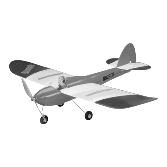
™ INSTRUCTION MANUAL ™ Wing Span - 39.5 in Wing Area - 288 sq in Weight - 13 oz Wing Loading - 6.5 oz/sq ft Fuse Length - 26 in © Copyright 2000 GPMZ0204 for GPMA1105 V1.0... - Page 2 GREAT PLANES MODEL MANUFACTURING COMPANY P.O. Box 788 Urbana, IL 61803 (217) 398-8970 WWW.GREATPLANES.COM READ THROUGH THIS MANUAL BEFORE STARTING CONSTRUCTION. IT CONTAINS IMPORTANT INSTRUCTIONS AND WARNINGS CONCERNING THE ASSEMBLY AND USE OF THIS MODEL.
-
Page 3: Table Of Contents
Building Supplies ................6 Thank you for purchasing the Great Planes Escapade. The METRIC CONVERSIONS .................6 Escapade is a lightweight, slow-flying Park Flyer that can be METRIC/INCH RULER ................7 flown just about anywhere there is an open area clear of PARTS DRAWINGS.................7 to 10 obstacles. - Page 4 2. You must assemble the Escapade according to the inspect all parts to make sure they are of acceptable instructions. Modifications may reduce performance. In quality. If any parts are missing, broken or defective, or cases where the instructions differ from the photos, the if you have any questions about building or flying this written instructions are correct.
-
Page 5: Additional Items Required
Substitute the “**” with the channel number you require. For Tele. (800) 435-9262 Fax (765) 741-0057 example, if the transmitter you plan to fly the Escapade with Or via the Internet at: is on channel 44, order receiver crystal HRCL2344. -
Page 6: Building Supplies
❏ Double-sided foam tape (GPMQ4440) for mounting receiver and speed control In addition to common household tools, here is the list of ❏ items used to build the Escapade. Sandpaper and sanding block ❏ Soldering iron and electrical solder ❏... -
Page 7: Metric/Inch Ruler
Inch Scale 0" 1" 2" 3" 4" 5" 6" 7" 100 110 120 130 140 150 160 170 180 Metric Scale 3/32" Balsa PARTS DRAWINGS (not actual size) #22 Crutch... - Page 8 3/32" Balsa #14 Servo Trays (2) Battery Holder Parts: #20 (2) Battery Holder Cover Parts: Optional Wing Struts (material not included, see page 21)
- Page 9 1/32" Plywood #6 Wing Braces (2) #7 (2) #8 Tab 3/32" Plywood #1 Landing Gear Former #2 Firewall #3 Front Former #4 (2) #5 Retainer...
- Page 10 1/32" Plywood #9 Tail Struts (2) #10 Doublers (2) #11Control Horns (2) #12 Spacers (2) 1/16" Balsa #13 Wing Struts (4) #23 Clear Plastic Windscreen...
-
Page 11: Important Building Notes
IMPORTANT BUILDING NOTES ASSEMBLY • Since the Escapade is made mostly of foam, and since CA Assemble the Tail Surfaces adhesives commonly used to build R/C model airplanes dissolve foam, CA should not be used when gluing foam parts. Therefore, 30-minute epoxy, which is compatible with foam, is used for most of the construction. - Page 12 ❏ 3. Lay the stab and elevator on your workbench with the ❏ slot in the elevator on the right side. Be certain there is a 2. Sand a bevel to the bottom of the leading edge of the elevator. The elevator is upside-down when the slot for the 1/16"...
- Page 13 ❏ 7. Use epoxy to glue the fin to the stab. Use a small builder's square to get the fin perpendicular to the stab, then use tape or small T-pins to hold them together until the epoxy hardens. ❏ 6. Glue the control horns into the slots. Be certain the elevator control horn is on the bottom and the rudder control horn is on the left (the stab and elevator are shown upside-down in the photo).
-
Page 14: Assemble The Battery Holder
Assemble the Battery Holder ❏ 2. Build the battery holder cover from the parts shown in the photo (4, 15, 16). Before gluing on 16, sand the top of 15 and the bottom of 16 at an angle. ❏ 1. Without using any glue, assemble all the 3/32" balsa parts of the battery holder (7 x 2, 18, 19, 20 x 2, 21) as ❏... -
Page 15: Assemble The Fuselage
the holder as shown. The tab will hold the cover in position, until removal or installation of the battery is required. Assemble the Fuselage ❏ 2. Temporarily fit the plywood landing gear former (1) into the fuselage. Be certain it is centered and in the groove in the fuselage. - Page 16 ❏ 3. Remove the landing gear former. Cut a slot, centered in the groove, from one mark to the other. Keep the piece of foam that was removed from the slot you cut, so it can be glued back into position after the former and the landing ❏...
- Page 17 ❏ 6. Test fit the front former and the landing gear former to the balsa crutch (22). Note that the tab on the front of the crutch should be on the right side. Sand the front of the crutch until it is the same width as the front former. ❏...
-
Page 18: Install The Servos
Install the Servos ❏ 1. Install the pushrods and guide tubes into the fuselage, but do not glue them into position until instructed to do so. The pushrods cross inside the fuselage. ❏ Refer to this sketch and the photo for the following 2. -
Page 19: Assemble The Wing
Assemble the Wing ❏ 1. Cut the slots in the wing for the wing struts. ❏ 3. Use a felt-tip pen to mark the center of the aft edge of the opening in the wing. Place the wing on your workbench resting on its trailing edge. - Page 20 fuselage sides, the wing is centered. Test fit the battery holder into fuse. If necessary, trim the edges of the opening in the wing or sand the sides of the battery holder until it fits in the fuse without disturbing the wing. ❏...
-
Page 21: Hook Up The Controls
9. Fit, then glue the wing struts to the other side of the inexperienced pilots: To improve rudder control and stall fuselage and the wing the same way. characteristics of the Escapade at slow speeds, use the templates on page 8 to make the optional wing struts from Hook Up the Controls 1/16"... - Page 22 ❏ 2. Connect the aft end of the pushrods to the control horns on the elevator and rudder. If necessary, make small ❏ bends in the pushrods to get them to align with the holes in 4. Use epoxy to glue the hinge into the slots you cut in the horns.
-
Page 23: Mount The Motor
❏ to accommodate the ends of the struts, but do not cut slots 7. Now that the servos have been positioned and the the stab. Glue the struts into position. controls are centered, glue the ends of the pushrod guide tubes to the slots in the fuselage and the slots in the landing gear former. - Page 24 ❏ ❏ 2. Glue both 1/32" plywood spacers (12) to the firewall 6. The pinion gear fits onto the motor shaft easier one as shown. Trim the top of the spacers even with the hole in way than it does the other. Using only your fingers (no tools), the firewall.
- Page 25 should not “coast” or freewheel indefinitely. If there is much resistance, back the motor out of the gearbox the same as you did before until the propeller spins as it should. ❏ 9. Reinstall the motor into the gearbox up to the line you marked.
-
Page 26: Final Assembly
Final Assembly ❏ 1. Trim the excess material from the aft edge of the molded plastic cowl. Cut a hole in the middle for the prop shaft, then cut a slot for the nose gear. ❏ 2. Mount the cowl to the fuse with tape. Any kind of tape will do, but we used 1/4"... - Page 27 ❏ 3. Cut six 1/8" retainers from the plastic tube. Mount the ❏ wheels to the landing gear with a retainer on both sides of 5. Glue the pilot together. Glue the pilot to the battery each wheel. Using care not to get any glue on the wheels, holder cover.
-
Page 28: Prepare The Model For Flying
small slits in the fuselage for the pointed tabs on the windscreen, then glue it into position. ❏ 7. Use double-sided foam mounting tape (GPMQ4440) to mount the speed control and receiver to the crutch inside the fuselage. Be certain to mount them in a location that will not interfere with the motor, servos or pushrods. -
Page 29: Balance The Model (C.g.)
Set up the Escapade so it has the following control surface throws shown in the chart that follows. The throws are throws: measured at the widest part of the control surface. - Page 30 ❏ 2. Lift the model right-side-up at the balance point you ❏ 1. Use a felt-tip pen or narrow strips of tape to mark the marked on the bottom of the wing. If the nose drops, the balance point on the bottom of the wing 1-1/2" [38mm] from model is nose-heavy and you must add weight to the tail.
-
Page 31: Identify Your Model
❏ experienced modeler to perform the inspection. Check to 4. After placing weight on the model where necessary, see that you have the radio installed correctly and that all recheck the C.G. to confirm that it is correct. the controls are connected properly. The motor must also be checked by confirming that the prop is rotating in the correct Identify Your Model direction and the motor sounds like it is reaching full power. -
Page 32: Performance Tips
(this is a necessity on glow-powered engines, but less critical on small electric models). The electric motor and motor battery used in the Escapade are very powerful and the spinning propeller has a lot of Using multiple battery packs for successive flights may momentum;... -
Page 33: Find A Safe Place To Fly
FIND A SAFE PLACE TO FLY models fly in the proximity of full-scale aircraft. Though the Escapade is a “Park Flyer,” the best place to fly 3. Where established, I will abide by the safety rules for the any model is at an AMA chartered club field. Club fields are... -
Page 34: Flying
Less experienced flyers crashing your model into a person, causing injury. Second should fly the Escapade only in calm (less than one mile per is the distraction from those who ask you questions while hour) conditions. -
Page 35: Flight
If you do pull too hard and you notice the model losing speed, release the elevator stick If the Escapade reaches a high enough altitude, you may and allow the model to regain airspeed. periodically cut off the motor power and glide. This may... -
Page 36: Rog (Rise Off Ground) Takeoff
After the airplane has gained adequate speed (this requires Until you are able to accurately judge how far the Escapade experience to gauge), gently pull back on the elevator stick can glide, it may be helpful to reserve some battery power allowing the airplane to become airborne. - Page 37 reserves power for safe landing. Built-in BEC eliminates unnecessary weight. 180-day warranty. GPMR2010 OTHER ITEMS AVAILABLE FROM GREAT PLANES ™ ElectriFly C-10 Micro Ultra High Frequency Electronic Speed Control Its solid-state design enables the ElectriFly C-10 Micro to ® ElectriFly Sanyo 8-Cell, 150 N-Size NiCd Pack offer a wide array of flight benefits in an incredibly compact, Assembled with genuine Sanyo N-size NiCd cells, this...
- Page 38 ElectriFly Sanyo 8-Cell, 270mAh NiCd Pack ElectriFly Sanyo 8-Cell, 350mAh NiCd Pack Compact but powerful, this ElectriFly battery pack arrives Its higher 350mAh capacity means more flight time – but assembled with connection lead and 2-pin connector. Best this ElectriFly NiCd pack remains featherlight at just 3.8 of all, it adds only 3.7 ounces of weight to your park flyer ounces, and continues the advantages of having Sanyo model! 1-year guarantee.
- Page 39 IDENTIFICATION TAG ElectriFly Peak Charger Designed for small, lightweight electrics and transmitter batteries, this charger can also be used with any 6- 8-cell NiCd or NiMH pack. It plugs into a power supply or cigarette lighter for fast charges. Pulsed current charging protects small packs from overheating.
- Page 40 BUILDING NOTES Kit Purchased Date: _______________________ Date Construction Finished: _________________ Where Purchased:_________________________ Finished Weight: __________________________ Date Construction Started: __________________ Date of First Flight: ________________________ FLIGHT LOG...
Need help?
Do you have a question about the Escapade and is the answer not in the manual?
Questions and answers