Table of Contents
Advertisement
Quick Links
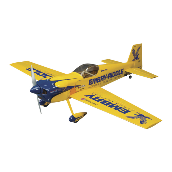
.46-.81/EP ALMOST-READY-TO-FLY SPORT SCALE AIRPLANE
Wingspan: 53 in [1350mm]
Wingspan: 53 in [1350mm]
Wing Area: 645 in
Wing Area: 645 in
2
2
[41.6dm
[41.6dm
2
2
]
]
Weight: 6 – 7 lb [2720 – 3180g]
Weight: 6 – 7 lb [2720 – 3180g]
Wing Loading: 21 – 25 oz/ft
Wing Loading: 21 – 25 oz/ft
2
2
[64 – 76g/dm
[64 – 76g/dm
Length: 57 5 in [1460mm]
Length: 57.5 in [1460mm]
Radio:
4-channel minimum with 4 to 5 servos and standard size receiver
Engine: .46 to .61 cu in [7.5 to 10cc] two-stroke,
.52 to .81 cu in [8.5 to 13.5cc] four-stroke
.80 (50-55-500) brushless out-runner motor
Great Planes
®
Model Manufacturing Co. guarantees this kit to
be free from defects in both material and workmanship at the date
of purchase. This warranty does not cover any component parts
damaged by use or modifi cation. In no case shall Great Planes'
liability exceed the original cost of the purchased kit. Further,
Great Planes reserves the right to change or modify this warranty
without notice.
In that Great Planes has no control over the fi nal assembly or
material used for fi nal assembly, no liability shall be assumed nor
accepted for any damage resulting from the use by the user of
the fi nal user-assembled product. By the act of using the user-
assembled product, the user accepts all resulting liability.
READ THROUGH THIS MANUAL BEFORE STARTING CONSTRUCTION. IT CONTAINS IMPORTANT
INSTRUCTIONS AND WARNINGS CONCERNING THE ASSEMBLY AND USE OF THIS MODEL.
Entire Contents © Copyright 2009
2
2
]
]
WARRANTY
INSTRUCTION MANUAL
If the buyer is not prepared to accept the liability associated
with the use of this product, the buyer is advised to return
this kit immediately in new and unused condition to the place
of purchase.
To make a warranty claim
send the defective part or
item to Hobby Services at:
Include a letter stating your name, return shipping address, as
much contact information as possible (daytime telephone number,
fax number, e-mail address), a detailed description of the problem
and a photocopy of the purchase receipt. Upon receipt of the
package the problem will be evaluated as quickly as possible.
Champaign, Illinois
(217) 398-8970, Ext 5
airsupport@greatplanes.com
Hobby Services
3002 N. Apollo Dr., Suite 1
Champaign, IL 61822 USA
GPMA1281MNL V1.0
Advertisement
Table of Contents

Related Manuals for GREAT PLANES matt chapman eagle 580


Summary of Contents for GREAT PLANES matt chapman eagle 580
-
Page 1: Instruction Manual
Champaign, IL 61822 USA item to Hobby Services at: In that Great Planes has no control over the fi nal assembly or Include a letter stating your name, return shipping address, as material used for fi nal assembly, no liability shall be assumed nor... -
Page 2: Table Of Contents
TABLE OF CONTENTS INTRODUCTION INTRODUCTION ............... 2 Congratulations on the purchase of the Great Planes Eagle 580 Matt Chapman .46-.81/EP ARF! This latest Matt AMA .................. 2 Chapman version has been designed to give even the most SAFETY PRECAUTIONS ..........3 selective pilots the 3D performance they are looking for as DECISIONS YOU MUST MAKE ........ -
Page 3: Safety Precautions
fi berglass Futaba Servo Extension 16" J (FUTM3955) ❏ parts. Vacuum the parts and the work area thoroughly after Great Planes 1" Servo Arm (GPMM1100) ❏ working with fi berglass parts. Dubro Servo Arms Super Strength Futaba J Long (8) (DUBM6670) ❏... -
Page 4: Power System Recommendations
This is the list of hardware and accessories required to ™ engine, or a RimFire .80 (50-55-500) brushless out-runner fi nish the Matt Chapman Eagle 580 .46-.81/EP ARF. Order motor. Recommended engine and motor order numbers are numbers are provided in parentheses: provided below: ❏... -
Page 5: Building Stand
BUILDING STAND hobby dealer or mail-order company. To locate a hobby dealer, visit the Great Planes web site at www.greatplanes.com. Choose “Where to Buy” at the bottom of the menu on the left side of the page. Follow the instructions provided on the page to locate a U.S., Canadian... -
Page 6: Kit Inspection
If any parts are missing or are not of acceptable quality, or if you need assistance with assembly, contact Product Support. When reporting defective or missing parts, use the part names exactly as they are written in the Kit Contents list. Great Planes Product Support: 3002 N. Apollo Drive, Suite 1 Champaign, IL 61822 Telephone: (217) 398-8970, ext. -
Page 7: Building Instructions
BUILDING INSTRUCTIONS Preparations ❏ 1. If you have not done so already, remove the major parts of the kit from the box and inspect for damage. If any parts are damaged or missing, contact Product Support at the address or telephone number listed in the “Kit Inspection” section on page 7. - Page 8 ❏ 6. Thread a nylon clevis 20 complete turns onto each 6" [152mm] pushrod. Slide a silicone clevis retainer onto each clevis and connect the clevises to the outer holes of two control horns. ❏ 4. Use the strings taped inside the aileron servo hatches ❏...
-
Page 9: Install The Tail Section
Install the Tail Section The horizontal stabilizer is a two-piece bolt-on design that can be taken off at any time by simply removing two screws. If, after this section, you decide it is easier to complete the model on your work table with the stab removed, feel free to do so as it will no longer be needed until it is time to set the control throws on the fi... -
Page 10: Install The Tail Servos & Pushrods
Install the Tail Servos and Pushrods A servo bay is provided in the tail of the plane for an aft mounted rudder servo. An aft mounted rudder servo will reduce or eliminate any tail weight needed to balance the airplane with a heavier engine installed. An additional 16" [406mm] servo extension is needed for an aft mounted rudder servo. - Page 11 ❏ 3. Cut three arms from two four-armed servo arms (a long servo arm will be needed on the elevator servo to achieve 3D control throw). Center the elevator and rudder servos with your radio system and install them onto the servos in the orientation shown with the servo arm screws.
-
Page 12: Assemble & Install The Landing Gear
Position the right elevator in the neutral position and cut off the excess pushrod 1" [25mm] behind the elevator servo arm. Join the two elevator pushrods together using two 5/32" [4mm] wheel collars, two 6-32 x 1/4" [6mm] SHCS and threadlocking compound. -
Page 13: Glow Engine Installation
Thread a 6-32 x 1/4" SHCS into each wheel collar and tighten the screws against the fl at spots on the axles. Be The Matt Chapman Eagle 580 .46 ARF is designed to be sure that the wheel rotates freely on the axle. Oil the axles fl... - Page 14 tray. Make a strap from the included hook and loop material TOP OF TANK by overlapping the mating ends by approximately 1" [25mm]. The total length of the strap will be determined by the size of your receiver battery. Fit the strap through the slots in the VENT motor mounting box as shown.
- Page 15 ❏ 6. Glue the plywood fuel tank brace to the fuselage as shown. The brace should be positioned against the back of the tank. ❏ 7. If you are installing the O.S. 81FS-a engine, you will need to trim away the nose gear bearing on the top side of the engine mount as shown.
- Page 16 useful). Roughen the outside of the included outer pushrod tube using 220-grit sandpaper. Slide the outer pushrod tube through the hole you drilled in the fi rewall and through one of the lightening holes in the second former. Fit the plywood outer pushrod tube support over the aft end of the pushrod tube, but do not glue it in place yet.
-
Page 17: Brushless Motor Installation
should be plugged with the included aluminum fuel line plug and will conveniently fi t into the fi ll line clip. Be sure to replace the fuel line plug after fi lling or draining the fuel tank. The pressure line will be installed onto the muffl er after the cowl installation section. - Page 18 7. Make a strap from the included hook and loop material by overlapping the mating ends by approximately 1" [25mm]. If you are installing the recommended Great Planes ESC, make the strap 6" [152mm] long. If you are using a different brand ESC, you can use the strap to secure the ESC to the ❏...
- Page 19 8. Secure the ESC tray to the underside of motor mounting box using the hook and loop strap. Use three #4 x 3/8" [9.5mm] self-tapping screws to attach the recommended Great Planes ESC to the ESC tray. ❏ 11. Attach the hook side from a package of self-adhesive hook and loop material (not included) to the center of the battery tray.
-
Page 20: Install The Receiver
mark this position on the tray for reference. Now would Install the Receiver also be a good time to confi rm that the motor will rotate the correct direction by temporarily powering up the motor using the ESC and your radio system (do not install a propeller yet!). -
Page 21: Finish The Model
Finish the Model ❏ 1. Before fi tting the cowl, make any cutouts necessary for your power system. If you are installing a glow engine, a cutout must be made for the engine head, exhaust, needle valve access, and cool air exit. -
Page 22: Apply The Decals
❏ ❏ 5. If you haven’t done so already, attach the muffl er to the 8. Install the canopy hatch by fi tting the canopy pins into their engine and connect the vent line from the fuel tank to the mating holes in the fi... -
Page 23: Get The Model Ready To Fly
batteries that have a higher voltage. Current will fl ow from GET THE MODEL READY TO FLY the higher voltage battery into the lower one, essentially “charging” the lower voltage battery pack. This situation will Install & Operate the Motor Battery likely cause heat and possibly a fi... -
Page 24: Set The Control Throws
(and Use a Great Planes AccuThrow (or a ruler) to accurately battery pack if applicable). measure and set the control throw of each control surface as ❏... -
Page 25: Balance The Model Laterally
Precision Magnetic Prop Balancer that side is heavy. Balance the airplane by adding weight to the (TOPQ5700) in the workshop and keep a Great Planes other wingtip. An airplane that has been laterally balanced Fingertip Prop Balancer (GPMQ5000) in our fl ight box. -
Page 26: Engine Safety Precautions
3) Where established, I will abide by the safety rules for the ENGINE SAFETY PRECAUTIONS fl ying site I use, and I will not willfully and deliberately fl y my models in a careless, reckless and/or dangerous manner. 5) I will not fl y my model unless it is identifi ed with my name Failure to follow these safety precautions may result and address or AMA number, on or in the model. -
Page 27: Checklist
CHECKLIST FLYING The Eagle 580 Matt Chapman .46-.81/EP ARF is a great- During the last few moments of preparation your mind may fl ying model that fl ies smoothly and predictably. The Eagle be elsewhere anticipating the excitement of the fi rst fl ight. does not, however, possess the self-recovery characteristics Because of this, you may be more likely to overlook certain of a primary R/C trainer and should be fl... -
Page 28: Flight
model gains speed decrease up elevator, allowing the tail improve your skills (though it is never a bad idea!), but more to come off the ground. One of the most important things to importantly so you do not surprise yourself by impulsively remember with a tail dragger is to always be ready to apply attempting a maneuver and suddenly fi... - Page 29 UPRIGHT FLAT SPINS VERTICAL HOVER Pull the nose up slightly and slowly decrease power. As the Fly a straight pass across the fi eld at 75ft high and 100ft out model slows to a few mph, slowly apply full left rudder and and pull the model vertical.
- Page 30 Knife Edge Loop and fl ying out Knife Edge. When done correctly, the plane pivots around the wingtip in a very small area. This maneuver can be done in either direction. OTHER ITEMS AVAILABLE FROM GREAT PLANES ™ Wingspan: 50 in (1270 mm) Wingspan: 58 in (1475 mm) Wing Area: 745 sq in (48.1 dm2)
- Page 31 O.S. ® 81FS-a Ringed 4-Stroke The 81FS-a delivers more performance power for sport pilots and more realistic fl ight for scale pilots — and for easy upgrades, features the same mounting bolt pattern, distance between crankcase and prop and throttle lever positions as the FS-70SII! A rubber O-ring on the muffl...
Need help?
Do you have a question about the matt chapman eagle 580 and is the answer not in the manual?
Questions and answers