
Related Manuals for ESAB Powercut 900


Summary of Contents for ESAB Powercut 900
- Page 1 Powercut 900 Manual & Mechanized Plasmarc Cutting Package Instruction Manual This manual provides complete instructions for MANUAL & MECHANIZED CONSOLES 0558008430 03/2014...
-
Page 2: User Responsibility
BE SUrE THIS INfOrMATION rEACHES THE OpErATOr. YOU CAN gET ExTrA COpIES THrOUgH YOUr SUppLIEr. CAUTION These INSTrUCTIONS are for experienced operators. If you are not fully familiar with the principles of operation and safe practices for arc welding and cutting equipment, we urge you to read our booklet, “precautions and Safe practices for Arc Welding, Cutting, and gouging,”... -
Page 3: Table Of Contents
4.5 Gouging with the Powercut 900 using the PT-38 torch ....... - Page 4 4.2 Cutting with the Powercut 900 using the PT-37 torch....... .
-
Page 5: Safety Precautions
SECTION 1 SAfETY prECAUTIONS Safety precautions Safety - English WArNINg: These Safety precautions are fIrES AND ExpLOSIONS -- Heat from for your protection. They summarize flames and arcs can start fires. Hot precautionary information from the slag or sparks can also cause fires and references listed in Additional Safety explosions. - Page 6 SECTION 1 SAfETY prECAUTIONS 1. Be sure the power source frame (chassis) is con- 3. Welders should use the following procedures to nected to the ground system of the input power. minimize exposure to EMF: 2. Connect the work piece to a good electrical A.
- Page 7 SECTION 1 SAfETY prECAUTIONS 5. WArNINg: This product, when used for welding 1. Always have qualified personnel perform the instal- or cutting, produces fumes or gases lation, troubleshooting, and maintenance work. which contain chemicals known to Do not perform any electrical work unless you are the State of California to cause birth qualified to perform such work.
- Page 8 SECTION 1 SAfETY prECAUTIONS MEANINg Of SYMBOLS - As used 5. AWS C5.5 - "Recommended Practices for Gas Tung- throughout this manual: Means Atten- sten Arc Welding“ tion! Be Alert! Your safety is involved. 6. AWS C5.6 - "Recommended Practices for Gas Metal Means immediate hazards which, Arc Welding"“...
-
Page 9: Safety - Spanish
SECTION 1 SEgUrIDAD Safety - Spanish La escoria puede estar caliente y desprenderse con velocidad. personas cercanas deberán usar ADVErTENCIA: Estas precauciones de gafas de seguridad y careta protectora. Seguridad son para su protección. Ellas hacen resumen de información prove- fUEgO Y ExpLOSIONES -- El calor de niente de las referencias listadas en la sección las flamas y el arco pueden ocacionar... - Page 10 SECTION 1 SEgUrIDAD 1. Asegúrese de que el chasis de la fuente de poder 3. Los soldadores deberán usar los siguientes proced- esté conectado a tierra através del sistema de imientos para minimizar exponerse al EMF: electricidad primario. 2. Conecte la pieza de trabajo a un buen sistema de A.
- Page 11 SECTION 1 SEgUrIDAD 5. ADVErTENCIA-- Este producto cuando se uti- 1. Siempre tenga personal cualificado para efec- liza para soldaduras o cortes, tuar l a instalación, diagnóstico, y mantenimiento produce humos o gases, los del equipo. No ejecute ningún trabajo eléctrico a cuales contienen químicos menos que usted esté...
- Page 12 SECTION 1 SEgUrIDAD SIgNIfICADO DE LOS SIMBOLOS -- Según usted avanza en la lectura de este folleto: Los Símbolos Sig- nifican ¡Atención! ¡Esté Alerta! Se trata de su seguridad. Significa riesgo inmediato que, de no ser evadido, puede resultar inmediatamente en serio daño personal o la muerte.
-
Page 13: Safety - French
SECTION 1 SÉCUrITÉ INCENDIES ET ExpLOSIONS -- La Safety - french chaleur provenant des flammes ou de AVErTISSEMENT : Ces règles de sécurité l'arc peut provoquer un incendie. Le ont pour but d'assurer votre protection. laitier incandescent ou les étincelles Ils récapitulent les informations de pré- peuvent également provoquer un caution provenant des références dans... - Page 14 SECTION 1 SÉCUrITÉ 1. Assurez-vous que le châssis de la source 3. Les soudeurs doivent suivre les procédures suivantes d'alimentation est branché au système de mise à pour minimiser l'exposition aux champs électriques la terre de l'alimentation d'entrée. et magnétiques : 2.
- Page 15 SECTION 1 SÉCUrITÉ 5. AVErTISSEMENT : Ce produit, lorsqu'il est utilisé ENTrETIEN DE L'ÉQUIpEMENT -- Un équipe- dans une opération de soudage ou de ment entretenu de façon défectueuse ou coupage, dégage des vapeurs ou des inadéquate peut causer des blessures gaz contenant des chimiques consid- graves ou mortelles.
- Page 16 SECTION 1 SÉCUrITÉ SIgNIfICATION DES SYMBOLES Ce symbole, utilisé partout dans ce manuel, signifie "Attention" ! Soyez vigilant ! Votre sécurité est en jeu. DANgEr Signifie un danger immédiat. La situation peut entraîner des blessures graves ou mortelles. AVErTISSEMENT Signifie un danger potentiel qui peut entraîner des blessures graves ou mortelles.
- Page 17 Powercut 900 MANUAL PLASMARC CUTTING PACKAGE...
-
Page 19: 2.0 General
CrEATE AN ELECTrIC SHOCK HAZArD. 2.0 general As shipped, the PowerCut 900 is fully assembled and ready to cut after being connected to input power and a source of compressed air. The Powercut package uses the heavy-duty PT-38 (Manual Plasma) torch to deliver cut- ting power for severing materials up to 1-1/4 inch (32 mm) thick. -
Page 20: Powercut 900 Manual Plasma
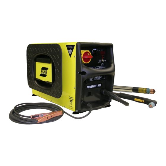
DESCrIpTION powercut 900 Manual plasma The Powercut 900 plasma cutting package combines the newly redesigned Powercut 900 console and PT-38 torch. The PT-38 plasma cutting torch is designed to provide increased performance and longer consumable life resulting in higher production rates at lower costs. -
Page 21: Manual Package Ordering Information
460 V PT-38 50 ft (15.2 m) ..................................0558008129 575 V PT-38 25 ft (7.6 m) Bilingual ..............................0558008132 The components that are included in the Powercut 900 manual packages may be purchased separately by using the ap- propriate P/N when placing orders. Individual part numbers are listed below:... -
Page 22: Optional Accessories
900/1300/1600 Water Separator ..p/n 0558007897 Improves air quality by removing water. powercut 900 Mechanized Conversion kit ..p/n 0558008284 Adds automated mechanized capability to an existing manual machine. Refer to mechanized section of this manual for CNC Interface connection. -
Page 23: Installation
SECTION 3 INSTALLATION INSTALLINg Or pLACINg ANY TYpE Of fILTErINg DEVICE WILL rE- WArNINg STrICT THE VOLUME Of INTAKE AIr, THErEBY SUBJECTINg THE pOWEr SOUrCE INTErNAL COMpONENTS TO OVErHEATINg. THE WArrANTY IS VOID If ANY TYpE Of fILTEr DEVICE IS USED. Installation general Proper installation is important for satisfactory and trouble-free operation of the Powercut cutting package. -
Page 24: Primary Input Connections
SOUrCE. primary Input Connections The Powercut 900 consoles are equipped with approximately 8 ft. (2.4 m) of 4-conductor input power cable for 3 phase connection. If single-phase connection is desired, cap the unused wire on the input power cable per chart below. -
Page 25: Section 3 Installation
Refer to Table 3-1 for recommended input conductors and line fuse sizes. Table 3-1. (powercut 900) recommended Sizes for Input Conductors and Line fuses... - Page 26 3.5.1 INpUT VOLTAgE CHANgEOVEr - 208/230 VOLTAgE 60 Hz UNITS ONLY 208 or 230 Mode The PowerCut 900, 208/230 vac, 60 Hz model, is factory set for 230 vac input. If using 208 vac input, the PowerCut 900 must be reconnected as follows before connecting to your input power: Remove cover.
-
Page 27: Provisions For Automation
SECTION 3 INSTALLATION 3.5.2 Input Air Connection / fuse replacement Connect your air supply to the inlet connection of the filter. Replace fuse with Slo-Blo, 2 Amp, 600 V only WArNINg MAKE SUrE THE pOWEr SOUrCE IS SWITCHED Off BEfOrE rEMOVINg fUSE. Pre-filtered DRY AIR SUPPLY (Customer Supplied) (90 - 150 psi / 6.2 - 10.3 bars) figure 3-3. -
Page 28: Secondary Output Connections For Manual Cutting
3-4. powercut Interconnection Diagram GROUND WArNINg MAKE SUrE pOWEr SWITCH ON CONSOLE IS IN Off pOSITION AND prIMArY INpUT pOWEr IS DE-ENErgIZED. pT-38 Torch Installation 1. Open torch lead access door on the front panel of the Powercut 900. Torch Lead Access Door... - Page 29 SECTION 3 INSTALLATION 2. Connect the torch cable receptacle to the panel receptacle. Check orientation of the sockets to ensure a correct fit. Panel Receptacle Torch Cable Male Receptacle 3. Connect the air hose to the quick-connect fitting. Place the strain relief in the square cutout in the front of the console.
- Page 30 SECTION 3 INSTALLATION...
-
Page 31: Operation
• Do NoT Touch aNy Torch parTs forwarD of The Torch haNDle (Nozzle, HEAT SHIELD, ELECTrODE, ETC.) WITH pOWEr SWITCH ON. Operation The PowerCut 900 will automatically tailor the arc for normal cutting, Expanded metal / grate cutting, and gouging operations. no manual switching is required. powercut 900 Controls power Switch. - Page 32 To clear over-current, the power must be shut off for 5 seconds and then turned back on. UP position CENTER position DOWN position Toggle Switch detail (Codes shown on non -"CE" units only) figure 4-2. powercut 900 Controls...
-
Page 33: Section 4 Operation
SECTION 4 OpErATION Help Codes (See Section 6.1, Troubleshooting for Causes and Solutions): Line voltage, idle +/- 15 % - line voltage has fluctuated +/- 15 %. Line voltage, cutting +/- 20 % - line voltage has fluctuated +/- 20 %. Control bias, +/- 15 V bias split - Control transformer supplying insufficient voltage to the control circuit. -
Page 34: Cutting With The Powercut 900 Using The Pt-38 Torch
CUTTINg ArEA. SpArKS AND HOT SLAg frOM THE CUTTINg OpErA- TION CAN DAMAgE THE UNIT. Cutting with the powercut 900 using the pT-38 torch Use the following procedures to cut with the PT-38 torch. Make sure that the wall disconnect switch is on and air is supplied to machine. - Page 35 SECTION 4 OpErATION After starting the cut, the torch should be maintained at a 5-15° forward angle. This angle is especially useful in helping to create a "drop" cut. When not using the stand-off guide, the nozzle should be held approximately 1/8 - 3/16 (3.2 mm - 4.8 mm) from the work.
-
Page 36: Stand-Off Guide
TO DrAg CUT WITH HIgHEr CUrrENTS grEATEr THAN 40 AMpS MAY CAUSE IMMEDIATE CATASTrOpHIC CONSUMABLE DAMAgE. Stand-off guide Refer to torch manual. Drag Cutting 40 Amp Refer to torch manual. gouging with the powercut 900 using the pT-38 torch Refer to torch manual. -
Page 37: Electrode Wear
ENErgIZED WITH HIgH VOLTAgE If THE TOrCH SWITCH IS ACCIDEN- TALLY CLOSED WHEN THE SHIELD IS rEMOVED. ALWAYS rEpLACE TOrCH WITH THE prOpEr TOrCH MANUfACTUrED BY ESAB SINCE IT ALONE CONTAINS ESAB'S SAfETY INTErLOCK. rEpLACE ELECTrODE BEfOrE WEAr BECOMES DEEpEr THAN .060"... - Page 38 SECTION 4 OpErATION...
-
Page 39: Powercut 900
Powercut 900 MECHANIZED PLASMARC CUTTING PACKAGE... -
Page 41: 2.0 General
SOLE COULD CrEATE AN ELECTrIC SHOCK HAZArD. 2.0 general As shipped, the PowerCut 900 is fully assembled and ready to cut after being connected to input power and a source of compressed air. The Powercut package uses the heavy-duty PT-37 (Mechanized Plasma) torch to de- liver cutting power for severing materials up to 7/8 inch (22 mm) thick. -
Page 42: Powercut 900 Mechanized Plasma
40 degrees C. Mechanized package Ordering Information The components that are included in the Powercut 900 mechanized packages may be purchased separately by using the appropriate P/N when placing orders. Individual part numbers are listed below:... -
Page 43: Pt-37 Torch Data
PT-37 Torch w/o rack 50' (15.2 m) ................................0558004897 WArNINg DO NOT USE OxYgEN WITH THIS TOrCH! A HAZArDOUS fIrE MAY rESULT. pT-37 Torch Data Powercut 900 mechanized plasma cutting packag- es use the PT-37 torch. For dimensions and break- down of parts, refer to torch manual. -
Page 44: Optional Accessories
900/1300/1600 Water Separator ..p/n 0558007897 Improves air quality by removing water. powercut 900 Mechanized Conversion kit ..p/n 0558008284 Adds automated mechanized capability to an existing manual machine. Refer to mechanized section of this manual for CNC Interface connection. -
Page 45: Installation
SECTION 3 INSTALLATION INSTALLINg Or pLACINg ANY TYpE Of fILTErINg DEVICE WILL rE- WArNINg STrICT THE VOLUME Of INTAKE AIr, THErEBY SUBJECTINg THE pOWEr SOUrCE INTErNAL COMpONENTS TO OVErHEATINg. THE WArrANTY IS VOID If ANY TYpE Of fILTEr DEVICE IS USED. Installation general Proper installation is important for satisfactory and trouble-free operation of the Powercut cutting package. -
Page 46: Primary Input Connections
SOUrCE. primary Input Connections The Powercut 900 consoles are equipped with approximately 8 ft. (2.4 m) of 4-conductor input power cable for 3 phase connection. If single-phase connection is desired, cap the unused wire on the input power cable per chart below. - Page 47 Refer to Table 3-2 for recommended input conductors and line fuse sizes. Table 3-1. (powercut 900) recommended Sizes for Input Conductors and Line fuses...
- Page 48 3.5.1 Input Voltage Changeover - 208/230 Voltage 60 Hz UNITS ONLY 208 or 230 Mode The PowerCut 900, 208/230 vac, 60 Hz model, is factory set for 230 vac input. If using 208 vac input, the PowerCut 900 must be reconnected as follows before connecting to your input power: 1.
-
Page 49: Cnc Interface Connection
SECTION 3 INSTALLATION 3.5.2 Input Air Connection Connect your air supply to the inlet connection of the filter. WArNINg MAKE SUrE THE pOWEr SOUrCE IS SWITCHED Off BEfOrE rEMOVINg fUSE. Replace fuse with Slo-Blo, 2 Amp, 600 V only Pre-filtered DRY AIR SUPPLY (Customer Supplied) (90 - 150 psi / 6.2 - 10.3 bars) figure 3-3. -
Page 50: Voltage Divider Adjustment
SECTION 3 INSTALLATION WArNINg MAKE SUrE pOWEr SWITCH ON CONSOLE IS IN Off pOSITION AND prIMArY INpUT pOWEr IS DE-ENErgIZED. Voltage Divider Adjustment It may be necessary to adjust the Voltage Divider or VDR to match the particular height control system. There are two de- fault settings for the PowerCut models as shipped from the factory: •... -
Page 51: Secondary Output Connections Mechanized Cutting
3-5. powercut Interconnection Diagram WArNINg MAKE SUrE pOWEr SWITCH ON CONSOLE IS IN Off pOSITION AND prIMArY INpUT pOWEr IS DE-ENErgIZED. pT-37 Torch Installation 1. Open torch lead access door on the front panel of the Powercut 900. Torch Lead Access Door... - Page 52 SECTION 3 INSTALLATION 2. Connect the torch cable receptacle to the panel receptacle. Check orientation of the sockets to ensure a correct fit. Panel Receptacle Torch Cable Male Receptacle 3. Connect the air hose to the quick-connect fitting. Place the strain relief in the square cutout in the front of the console.
-
Page 53: Operation
80 psig (5.5 bar). Pressure is indicated on the display screen. Output Current Control. Adjustable from 20 to 60 amperes. For settings refer to cut data charts in the torch manual. figure 4-1. powercut 900 Controls... - Page 54 "Help Code" menu on the front panel (non-"CE" units only) or in Section 4.1.F and in Troubleshooting Section 6.1. UP position CENTER position DOWN position Toggle Switch detail (Codes shown on non -"CE" units only) figure 4-2. powercut 900 Controls...
- Page 55 SECTION 4 OpErATION Note: All fault signals will remain on for a minimum of 10 seconds. If fault clears, all will reset automatically except for over-current. To clear over-current, the power must be shut off for 5 seconds and then turned back on. Help Codes (See Section 6.1, Troubleshooting for Causes and Solutions): Line voltage, idle +/- 15 % - line voltage has fluctuated +/- 15 %.
-
Page 56: Cutting With The Powercut 900 Using The Pt-37 Torch
TOrCH WITH THE prOpEr TOrCH MANUfACTUrED BY ESAB SINCE IT ALONE CONTAINS ESAB'S SAfETY INTErLOCK. Cutting with the powercut 900 using the pT-37 torch A. Make sure that the wall disconnect switch is on and air is supplied to machine. - Page 57 Powercut 900 MAINTENANCE TROUBLESHOOTING SCHEMATIC DIAGRAMS REPLACEMENT PARTS...
-
Page 59: General
SECTION 5 MAINTENANCE BE SUrE THAT THE WALL DISCONNECT SWITCH Or WALL CIrCUIT WArNINg BrEAKEr IS OpEN BEfOrE ATTEMpTINg ANY INSpECTION Or WOrK INSIDE Of THE pOWErCUT. general If this equipment does not operate properly, stop work immediately and investigate the cause of the malfunc- tion. -
Page 60: Common Cutting Problems
Listed below are common cutting problems followed by the probable cause of each. If problems are determined to be caused by the Powercut, refer to the maintenance section of this manual. If the problem is not corrected after referring to the maintenance section, contact your ESAB distributor. A. Insufficient penetration. -
Page 61: Igbt Handling
SECTION 5 MAINTENANCE IgBT Handling Since IGBT gates are insulated from any other conducting region, care should be taken to prevent static build up, which could possibly damage gate oxides. All IGBT modules are shipped from the factory with conductive foam contacting the gate and emitter sense pins. - Page 62 SECTION 5 MAINTENANCE...
-
Page 63: Troubleshooting
SECTION 6 TrOUBLESHOOTINg ELECTrIC SHOCK CAN KILL! BE SUrE THAT ALL prIMArY pOWEr TO WArNINg THE MACHINE HAS BEEN ExTErNALLY DISCONNECTED. OpEN THE LINE (WALL) DISCONNECT SWITCH Or CIrCUIT BrEAKEr BEfOrE AT- TEMpTINg INSpECTION Or WOrK INSIDE Of THE pOWEr SOUrCE. VOLTAgES IN pLASMA CUTTINg EQUIpMENT ArE HIgH ENOUgH WArNINg TO CAUSE SErIOUS INJUrY Or pOSSIBLY DEATH. -
Page 64: List Of Help Codes
SECTION 6 TrOUBLESHOOTINg List of Help Codes Code Error Cause Solution Line voltage, idle +/- 15 % Supply line voltage either dropped or Check voltage supply. exceeded nominal input setting while idle. Line voltage, cutting +/- 20 % Supply line voltage either dropped or ex- Check voltage supply. -
Page 65: Replacement Parts
Ordering To ensure proper operation, it is recommended that only genuine ESAB parts and products be used with this equipment. The use of non-ESAB parts may void your warranty. Replacement parts may be ordered from your ESAB Distributor. -
Page 66: Torque Recommendations
SECTION 7 rEpLACEMENT pArTS Torque recommendations rECOMMENDED TOrQUES ( IN/LBS ±10% ) SYMBOL / DESCrIpTION MOUNT TErMINAL BR101 Q101,102 BR102 C101-102 R1,2,3,4,5 HEATSINK WORK , GND1 GND2 GND3 Hand GND-A,B,C,D,E,F,G,H,J GND K,L PCB1 - POTENTIOMETERS PCB2,3 PCB2 - TB1,2 PCB2 - J16 PCB3 - TB4 PCB3 - TB3,5,6 PCB7... -
Page 67: Selecting Air Pressure Units Of Measure
SECTION 7 rEpLACEMENT pArTS Selecting Air pressure Units of Measure 1. Set SW1-1 dip switch for desired air pressure units of measure. • PSI - “OPEN” • BAR - Not Open 2. SW1-2 is not used. 3. Verify SW2 - 1,2 dip switches are in the “open” position for proper operation. Control/Display Board Assembly CONTrOL/DISpLAY BOArD ASSEMBLY P/N 0558038317... -
Page 68: Primary Power Board Assembly
SECTION 7 rEpLACEMENT pArTS primary power Board Assembly prIMArY pOWEr BOArD ASSEMBLY P/N 0558038355, 0558038371, 0558038356, 0558038345 Before installation: 1. Disconnect input power to machine. 2. Verify position of dip switches. Settings: 1. Verify SW1 - 1,2 dip switches are in the “closed” position for proper operation. open Important Note: This replacement pc board may have a... -
Page 69: Secondary Power Board Assembly
SECTION 7 rEpLACEMENT pArTS Secondary power Board Assembly SECONDArY pOWEr BOArD ASSEMBLY P/N 0558038358 Before installation: 1. Disconnect input power to machine. TB6 stud TB5 stud Voltage Divider Trimpot (mechanized versions) TB3 stud Important Note: This replacement pc board may have 10-32 (fine) studs for TB3, TB5 and TB6. - Page 70 NOTES...
-
Page 71: Revision History
rEVISION HISTOrY 1. Preliminary release of this manual: 05/2009 2. 08/2009 - Minor changes, Updated replacement parts and schematics. 3. 11/2009 - Added 575V designations in sect 2, added cnc cable in sect 2, updated fig. 3-5, updated replacement parts and schematics. 4. - Page 72 ESAB Welding & Cutting products, florence, SC Welding Equipment COMMUNICATION gUIDE - CUSTOMEr SErVICES CUSTOMER SERVICE QUESTIONS: Telephone: (800)362-7080 / Fax: (800) 634-7548 Hours: 8:00 AM to 7:00 PM EST Order Entry Product Availability Pricing Order Information Returns ENGINEERING SERVICE:...
Need help?
Do you have a question about the Powercut 900 and is the answer not in the manual?
Questions and answers