Table of Contents
Advertisement
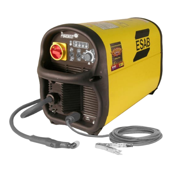
POWERCUT-1250 / 1500
MANUAL & MECHANIZED PLASMARC CUTTING PACKAGE
Installation, Operation and Service Manual (GB)
This manual provides complete instructions for MANUAL CONSOLES starting with Serial Number PxxJ245xxx, May 2003:
This manual provides complete instructions for MECHANIZED CONSOLES starting with Serial Number PxxJ316xxx, May 2003:
0558004232
Advertisement
Table of Contents

Subscribe to Our Youtube Channel
Related Manuals for ESAB POWERCUT-1250


Summary of Contents for ESAB POWERCUT-1250
- Page 1 POWERCUT-1250 / 1500 MANUAL & MECHANIZED PLASMARC CUTTING PACKAGE Installation, Operation and Service Manual (GB) This manual provides complete instructions for MANUAL CONSOLES starting with Serial Number PxxJ245xxx, May 2003: This manual provides complete instructions for MECHANIZED CONSOLES starting with Serial Number PxxJ316xxx, May 2003:...
-
Page 2: User Responsibility
BE SUrE THIS INfOrMATION rEACHES THE OPErATOr. YOU CAN GET ExTrA COPIES THrOUGH YOUr SUPPLIEr. CAUTION These INSTrUCTIONS are for experienced operators. If you are not fully familiar with the principles of operation and safe practices for arc welding and cutting equipment, we urge you to read our booklet, “Precautions and Safe Practices for Arc Welding, Cutting, and Gouging,”... -
Page 3: Table Of Contents
Secondary Output Connections for Manual Plasma ..............202 SECTION 3 OPErATION ............................. 203 Operation ..............................203 PowerCut-1250 / 1500 Controls ......................203 PT-32EH Torches used with Manual Plasma Only ............... 205 PT-32EH Possible Cutting Issues ......................210 POWErCUT-1250/1500 MECHANIZED PLASMArC CUTTING PACKAGE SECTION 1 DESCrIPTION ............................ - Page 4 TABLE Of CONTENTS SECTION TITLE PAGE PArAGrAPH SECTION 4 MAINTENANCE ......................363 General ............................... 355 Inspection and Cleaning ........................355 Common Cutting Problems ........................ 356 IGBT Handling & Replacement......................357 SECTION 5 TrOUBLESHOOTING ....................367 Troubleshooting ............................. 359 Troubleshooting Guide ........................360 Reference Voltage Checks ........................
-
Page 5: Safety Precautions
SAfETY PrECAUTIONS Safety Precautions Users of ESAB welding and plasma cutting equipment have the ultimate responsibility for ensuring that anyone who works on or near the equipment observes all the relevant safety precautions. Safety precautions must meet the requirements that apply to this type of welding or plasma cutting equipment. The following recommendations should be observed in addition to the standard regulations that apply to the workplace. - Page 6 SAfETY PrECAUTIONS WELDING AND PLASMA CUTTING CAN BE INJUrIOUS TO YOUrSELf AND WArNING OTHErS. TAKE PrECAUTIONS WHEN WELDING Or CUTTING. ASK fOr YOUr EMPLOYEr’S SAfETY PrACTICES WHICH SHOULD BE BASED ON MANUfACTUrErS’ HAZArD DATA. ELECTrIC SHOCK - Can kill. - Install and earth (ground) the welding or plasma cutting unit in accordance with applicable standards. - Do not touch live electrical parts or electrodes with bare skin, wet gloves or wet clothing.
- Page 7 POWERCUT-1250 / 1500 MANUAL PLASMARC CUTTING PACKAGE...
-
Page 9: Description
SECTION 1 DESCrIPTION 1.0 GENErAL The Powercut-1250 / 1500 is a compact, completely self-contained plasma cutting system. As shipped, the system is fully assembled and ready to cut after being Use only the ESAB PT-32EH Plasmarc torch with this console. Use of torches not connected to input power and a source of compressed air (90-150 psi / 6.2 to... -
Page 10: Manual Plasma
PowerCut-1250, 460 V, 50’ (15.2m) PT- 32EH ......0558005333 (76.2) 1.500 (38.1) (---) The components that are included in the Powercut-1250 packages (Console, Torch, Spare Parts Kit) may be purchased separately by using the appropriate P/N when placing orders. Individual part numbers are listed below: Consoles: PowerCut-1250 (208)230/460 V, 50/60 Hz, 1/3-ph .... -
Page 11: Ordering Information
SECTION 1 DESCrIPTION 1.2.2 PC-1500 MANUAL PLASMA The PowerCut-1500 plasma cutting package combines the proven reliability of the PowerCut-1500 with the newly designed PT-32EH torch. The very strong composite case material makes the PowerCut-1500 an excellent addition to any equipment rental fleet. The PT-32EH plasma cutting torch is designed to provide increased performance and longer consumable life resulting in higher production rates at lower costs. -
Page 12: Spare Parts Kits
Lubricant 17672 (0558000443) The PowerCut-1250 comes out of the box ready to go. The torch is attached with parts in place, primary cord is attached and the filter/regulator is installed. Just hook up the air, power and begin cutting. (NOTE: Part numbers in parenthesis apply to "CE"/European units only.) -
Page 13: Optional Accessories
SECTION 1 DESCrIPTION Optional Accessories: 70 A Spare Parts Kit ............................0558003508 70 A 400 V LHS Spare Parts Kit, "CE" units .....................0558003560 90 A Spare Parts Kit ............................0558003062 90 A 400 V LHS Spare Parts Kit, "CE" units .....................0558003557 Plasma flow Measuring Kit: This valuable troubleshooting tool allows measurement of the actual plasma gas flow through the torch ...................... - Page 14 SECTION 1 DESCrIPTION...
-
Page 15: Installation
SECTION 2 INSTALLATION INSTALLATION - MANUAL PLASMA CUTTING PACKAGE GENErAL Proper installation is important for satisfactory and trouble-free operation of the PowerCut cutting package. It is suggested that each step in this section be studied carefully and followed closely. EQUIPMENT rEQUIrED A source of clean, dry air that supplies 350 cfh (165.2 l/m) at 80 psig (5.5 bar) is Installing or placing any type of filtering required for the cutting operation. -
Page 16: Primary Electrical Input Connections - Manual Plasma Cutting Packages
INSTALLATION PrIMArY ELECTrICAL INPUT CONNECTIONS - MANUAL PLASMA CUTTING PACKAGE The PowerCut-1250 / 1500 consoles are equipped with approximately 10-ft. of 4-conductor input power cable for 3-phase connection. If single-phase connection ELECTrIC SHOCK CAN KILL! Precaution- ary measures should be taken to provide is desired, tape back the red (lt. -
Page 17: Section 2 Installation
SECTION 2 INSTALLATION Before connecting to input power, make sure there is a line (wall) disconnect switch with fuses or circuit breakers at the main power panel. You may either use the factory-installed input power cable (4/c, type SO (90 °C), 10 ft (3.1 m) length) ELECTrIC SHOCK CAN KILL! Before making or provide your own input power leads. - Page 18 SECTION 2 INSTALLATION SECONDArY OUTPUT CONNECTIONS fOr MANUAL CUTTING The torch comes factory installed. Clamp the work cable to the workpiece. Be sure the workpiece is connected to an approved earth ground with a properly sized ground cable. WORK SAFETY GROUND PT-32EH figure 2-2.
-
Page 19: Operation
SECTION 3 OPErATION figure 3-1A. PowerCut-1250 / 1500 Controls OPErATION PowerCut-1250 / 1500 CONTrOLS Power Switch. When placed in ON position, the white power light will glow indicat- ing control circuit is energized. Air Test Switch. When placed in TEST position, air filter-regulator can be adjusted to desired pressure (80 psig / 5.5 bar) before cutting operations. -
Page 20: Section 3 Operation
OPErATION figure 3-1B. PowerCut-1250 / 1500 Controls D. Output Current Control. Adjustable from 20 to 70 amperes on Powercut-1250. Adjustable from 20 to 90 amperes on Powercut-1500. E. Power "ON" Indicator: Illuminates whenever the front panel power switch is in the ON position. - Page 21 SECTION 3 OPErATION PT-32EH TOrCH USED WITH MANUAL PLASMA ONLY ELECTrIC SHOCK can kill. 3.2.1 CUTTING WITH THE POWErCUT-1250 / 1500 USING THE • Do NOT operate the unit with the cover PT-32EH TOrCH (MANUAL PLASMA ONLY) removed. • Do NOT apply power to the unit while holding or carrying the unit. Use the following procedures to cut with the PT-32EH torch.
- Page 22 SECTION 3 OPErATION After starting the cut, the torch should be maintained at a 5-15° forward angle. This angle is especially useful in helping to create a "drop" cut. When not using the stand-off guide, the nozzle should be held approximately 1/4 inch (6.4mm) from the work. DIrECTION figure 3-2a.
- Page 23 HIGH CURRENT DRAG CUTTING If drag cutting is desired on materials above 3/8” (9.5mm) thick, be sure that the 70 amp / 90 amp nozzle is installed in the PT-32EH torch. Attach ESAB's stand-off guide and operate as shown in Figure 3.3.
- Page 24 VALVE PIN closed when the shield is removed. Always replace torch with the with the proper ELECTRODE torch manufactured by ESAB since it alone contains ESAB's patented safety interlock. NOZZLE PLACE NOZZLE INTO HEAT...
- Page 25 SECTION 3 OPErATION ADJUST GUIDE BY TURNING IN A CLOCKWISE DIRECTION ONLY. THIS WILL PREVENT ACCIDENTAL LOOSENING OF SHIELD. IF GUIDE IS TOO TIGHT ON SHIELD, OPEN SLOT WITH SCREWDRIVER. STEEL GUARD STAND OFF GUIDE P/N 0558002393 THIN GAUGE MATERIALS CAN BE CUT WITH 1/16"...
-
Page 26: Pt-32Eh Possible Cutting Issues
SECTION 3 OPErATION PT-32EH POSSIBLE CUTTING ISSUES Replace when eroded beyond .06"(1.5mm) Depth. rEPLACE ELECTrODE BEfOrE PITTING BECOMES DEEPEr THAN .06 INCH (1.5 figure 3-6. Electrode Wear Limit NOTE: When replacing the nozzle, always inspect the electrode for wear. If more than .06"... - Page 27 POWERCUT-1250 / 1500 MECHANIZED PLASMARC CUTTING PACKAGE...
-
Page 29: Description
DESCrIPTION 1.0 GENErAL The Powercut-1250 / 1500 is a compact, completely self-contained plasma cut- ting system. The system is shipped with the PT-21AMX mechanized torch. Torch must be wired to the console before operation. See section 2.6.1. The system is... -
Page 30: Mechanized Plasma
400 V, “CE” 50’ (15.2m) PT-21NR ............0558005497 0.250 (6.35) 85 (2159) 101 (2565.4) The components that are included in the Powercut-1250 packages (Console, 0.500 (12.7) 30 (762) 39 (990.6) Torch, Spare Parts Kit, Torch Holder Assembly & Interface Cable) may be 0.750 (19.05) - Page 31 SECTION 1 DESCrIPTION 1.2.2 PC-1500 MECHANIZED PLASMA The PowerCut-1500 plasma cutting package combines the proven reliability of the PowerCut-1500 with the newly designed PT-21AMX torch. The PT-21AMX plasma cutting torch is designed to provide increased performance and longer consumable life resulting in higher production rates at lower costs.
- Page 32 SECTION 1 DESCrIPTION 1.2.3 SPArE PArTS / OPTIONAL ACCESSOrIES (PC-1250 / 1500 MECHANIZED PLASMA) Contents of PT-21AMX Spare Parts Kit, Optional Accessories: P/N 21370 (2461001) 50 Amp Torch Holder Assembly ............16V83 (0558004250) 50 amp Spare Parts Kit ...............21370 (2461001) 70 amp Spare Parts Kit ............
- Page 33 SECTION 1 DESCrIPTION Electrode - 21150 (0558004262) Heat Shield Baffle Tube - 21374 (4485838) 70/90 amp - 21326 (4485831) 30/50 amp -21447 (4485832) O-Ring - 488157 (4485841) Cutting Nozzle (see appropriate spare parts kit for p/n) Insulator - 21373 (4485837) Electrode AdaptorAssembly - 21332 (4485840) Torch Body Assembly -...
-
Page 34: Section 1 Description
SECTION 1 DESCrIPTION Cutting Parameters for the PT-21AMx Torch 70AMP Data, Nozzle P/N 21329 (4485834), Heat Shield P/N 21326 (4485831) Voltage “NR” indicates piercing is not recommended Metal Thickness 40/50AMP Data, Nozzle P/N 21330 (4485833), Heat Shield P/N 21447 (4485832) Voltage “NR”... -
Page 35: Installation
SECTION 2 INSTALLATION INSTALLATION - MECHANIZED PLASMA CUTTING PACKAGE GENErAL Proper installation is important for satisfactory and trouble-free operation of the PowerCut cutting package. It is suggested that each step in this section be Installing or placing any type of filtering studied carefully and followed closely. - Page 36 INSTALLATION PrIMArY ELECTrICAL INPUT CONNECTIONS - MECHANIZED PLASMA CUTTING PACKAGE The PowerCut-1250 / 1500 consoles are equipped with approximately 10-ft. of ELECTrIC SHOCK CAN KILL! Precaution- 4-conductor input power cable for 3-phase connection. If single-phase connection ary measures should be taken to provide is desired, tape back the red (lt.
- Page 37 SECTION 2 INSTALLATION Before connecting to input power, make sure there is a line (wall) disconnect switch with fuses or circuit breakers at the main power panel. You may either use the factory-installed input power cable (4/c, type SO (90 °C), 10 ft (3.1 m) length) or provide your own input power leads.
- Page 38 Installation, Operation, and Maintenance Manual for the SECTION 2 INSTALLATION SHADOW 2.6 SECONDArY OUTPUT CONNECTIONS fOr MECHANIZED CUTTING GANTRY SHAPE CUTTING MACHINE TORCH CABLE PT-21 AMX Clamp the work cable to the workpiece. Be sure the workpiece is connected to an SAFETY GROUND figure 2-4.
- Page 39 SECTION 2 INSTALLATION B. Remove nut on torch cable assembly. C. Insert torch cable assembly through opening in cover. D. Re-attach cable nut and tighten. E. Pull an adequate amount of hose through the cover to allow ease of hose connections. F.
- Page 40 SECTION 2 INSTALLATION...
-
Page 41: Operation
SECTION 3 OPErATION OPErATION PowerCut-1250 / 1500 CONTrOLS NOTE: See Section 3.1.C, for complete operation instructions NOTE: Trigger Lock Switch. Mechanized Operation using the PT- 21AMx torch - In mechanized operation the Trigger Lock function disabled. In- stead, the switch functions as an "Auto- restrike"... - Page 42 SECTION 3 OPErATION PT-21AMx TOrCH USED WITH MECHANIZED PLASMA ONLY 1. The seat comes assembled to the front end of the torch. If the seat becomes damaged, the torch body must be replaced. DO NOT attempt to remove the Make sure power switch on the POWErCUT is in the Off position before working on seat from torch body.
- Page 43 SECTION 3 OPErATION 4. Install nozzle onto the electrode assembly by inserting small shoulder on electrode insulator into nozzle’s rear opening. Place nozzle and electrode assembly into the heat shield. If front end of the torch is facing down as normal in a setup, the nozzle and electrode assembly can be stacked in the heat shield and then assembled to the torch.
-
Page 44: Pt-21Amx Possible Cutting Issues
SECTION 3 OPErATION PT-21AMx POSSIBLE CUTTING ISSUES Replace when eroded beyond .06"(1.5mm) Depth. rEPLACE ELECTrODE BEfOrE PITTING BECOMES DEEPEr THAN .06 INCH (1.5 figure 3-1. Electrode Wear Limit NOTE: When replacing the nozzle, always inspect the electrode for wear. If more than .06"...
Need help?
Do you have a question about the POWERCUT-1250 and is the answer not in the manual?
Questions and answers